Interfacing an AVR controller to a GPS Mobile Phone
Update: Part II Using Google Maps with a Mobile GPS Tracker is online.
My goal is to build a kind of a mobile tracker. There are many different use cases you can think of but one of the obvious is a device, that is able to report where it is. This device can be put in your car and it could trigger an alarm, if the car got stolen. Actually it could tell you where it is.
There are already mobile tracking devices out there, but they seemed to be too expensive and too closed for my needs. Another option is one of these new Nokia N95 which have built-in GPS. They are really nice, but about 600€, which is not a bargain. So I decided to do my own.
Materials
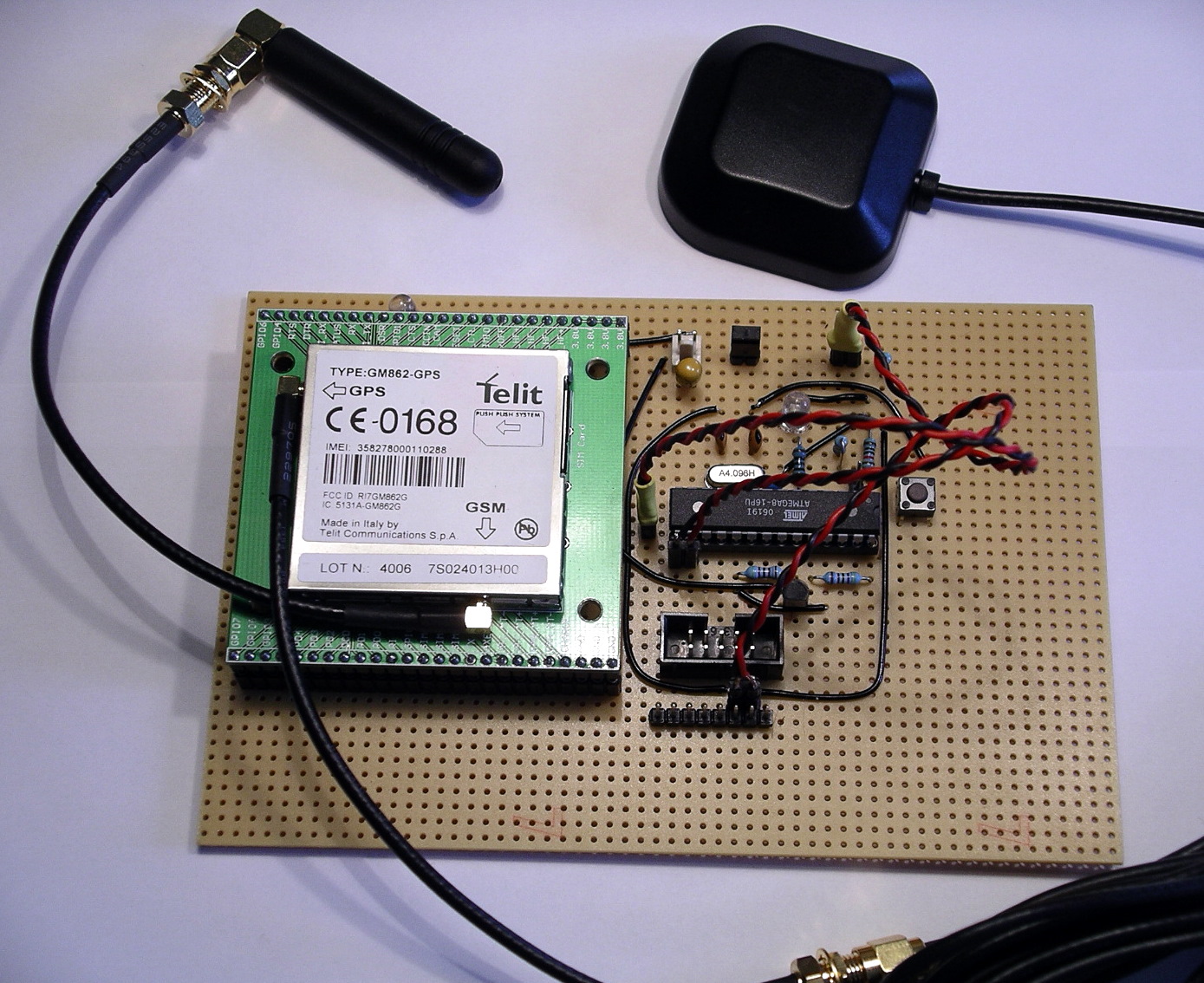
So my first idea was to combine a microcontroller with a GSM and a GPS modul. There are a lot of these modules over at Sparkfun, for example. Looking through their shop I found the Telit GM862, which is a GSM modul with an built in GPS receiver. That is what I wanted. And they sell great break out boards to make it easier for hobbyist to access these modules.
Here are some of the features of this GSM-GPS module:
- Quad band GSM
- 17mA average stand-by, 3.5mA in low-power mode
- 250mA average operating current
- SiRF III GPS Receiver Built In
- Data, Voice, SMS, and Fax
- Data speeds up to 57.6kbps
- Supply voltage : 3.4-4.2V
- CMOS Camera Capable
- Python Interpreter built-in
Voice means you are not limited to mobile tracker applications. You could attach a speaker and a microphone to build a complete mobile phone!
So here is a list of what I purchased to get the first integration done.
- Telit GM862-GPS modul, roundsolutions: 126€, or Sparkfun: CEL-07917, $183.95
- GM862 Evaluation Board, Sparkfun: CEL-00277, $29.95
- Quad band antenna, Sparkfun: CEL-00675, $7.95
- GPS antenna 3V, Sparkfun: GPS-00464, $14.95
- 2 interface cables for antenna, Sparkfun: GPS-00285, $8.95
- optional: PolymerLithium Ion Batteries, Sparkfun: PRT-00341, $7.95
- optional: LiPoly Charger, Sparkfun: PRT-00726, $16.95
- ATmega8 microcontroller, ca. 2€
- Resistors: 100, 10k, 22k, 27k, 2 x 47k, 2 x 100k, ca. 1€
- Capacitors: 2 x 22p, 100n, 10u, ca. 2€
- LED, 0.10€
- Transistor, BC337, 0.10€
- Prototyping board, 3€
- optional: bread board
Summing up you get all parts at about 220€ or $286. Ouch! Who said, that tinkering with electronics is a cheap passion? But again, if you go this way, you can implement anything you can think of.
Circuit
Looking at the specs for the GM862, you realize, that it is more complex as you might have thought. A problem for me, still a beginner in electronics, were the different voltages used for the module. The power supply has to be 3.4-4.2V. Thats ok as an AVR can run on that voltage. But the serial port requires lower levels, 2.8V (CMOS). That means, you can not connect the UART of the controller directly to the module. You have to do some level translation. Fortunately this has already been solved over at Trackbox2.
Another point to mention is the power supply itself. It requires at least 2A for peaks. I used a LiPoly rechargable battery, which perfectly fits my needs. If you have to use 5V supply, you will have to use a capable voltage regulator and you have to deal with the CMOS voltage level issue as well.
As you can see, there are very few connections really required to the GM862. You have to connect the following on the breakout board:
- RX, seriell modem communication
- TX, seriell modem communication
- RTS to ground, no handshake is used.
- Status LED
- On/off to power on the module
- VCC and GND
Please keep in mind, that this is not an enterprise grade and production like circuit, so read any spec and guide before you assemble your components. You have been warned.
Operation
For now I am able to switch the module on and off, send text SMS through the module and fetch GPS positions from it. Here is an example GPS response:
Request GPS AT$GPSACP got: AT$GPSACP GPSACP: 131924.999,5333.9291N,00954.8841E,2.6,34.0,3,29.78,0.32,0.17,130707,07 OK
So now you know where I am living
Conclusion
That’s it so far. It cost me quite some energy and money but was worth it. Next time more on software and how to talk to the GSM module.
Links
- Part Two:Using Google Maps with a Mobile GPS Tracker
- Trackbox2, great information about interfacing an AVR to a GM862, helped me a lot. In german.
- Portable Rotary Cellular Phone, tutorial at Sparkfun on how to use a GM862. There is also a forum, that has informations about GSM and GPS.
- roundsolutions.de, retailer for the GM862 with a great forum.
- Telit, all specs and guides for the GM862.
Downloads
- Eagle schematics: beacon.zip
- Eagle schematics as png: beacon.png


July 14th, 2007 at 19:16
Nice project, I was thinking of doing the same thing with an old gps and a gsm modem. (Same as the Trackbox by the looks of it) I was looking at the ATmega128 due to the two serial ports, but seems like overkill. Only just started looking at AVR and yet to get my hands dirty, could you use a AT2313 which seem quite popular?
July 14th, 2007 at 20:08
The ATtiny2313 is maybe a bit limitted (2k flash, 128 bytes SRAM). I am using the ATmega8 (8k flash, 1k SRAM) which is sufficient until now. Communication is done with a hardware and a software serial port. One is attached to the modem, the other, for debugging and monitoring is attached to my PC, so you don’t have to have 2 hardware UARTs.
July 16th, 2007 at 16:48
For your serial IO, you could step down the voltage for TXD with 2 diodes (0.6V drop per diode) instead of the resistor divider it appears you’ve done. And you wouldn’t need anything at all for RXD if the output is true 2.2V since that reads as logic high for most 3.3V inputs. However, I can’t read the schem very well because the labels are too small so I’m guessing at what you did.
July 16th, 2007 at 18:22
You don’t need a uController, the Telit module has Python built-in.
This is what you need to do:
1) Insert a SIM card
2) Write a python script to get the GPS position
3) setup the module to boot the python script (AT#ESCRIPT = “gps_sms.py”)
3) send the GPS position via SMS through the python script
I did this last week with the same module for another purpose.
All you really need for this circuit is a power supply / charger
July 16th, 2007 at 20:11
[…] вы точно последуете его (http://tinkerlog.com/2007/07/13/interfacing-an-avr-controller-to-a-gps-mobile-phone/) инструкции, то в итоге у вас получится нечто, […]
July 16th, 2007 at 21:36
It is worth noting that the GM862 has an embedded charging circuit (for details see http://www.telit.co.it/data/uploads_EN/products/80272st10019a_GM862_Product_Description_r5.pdf page 16) although I have not used it myself.
Using embedded Python would save the extra cost / complexity of a separate microcontroller. However developing using Python can be tricky (no easy debugging capability) - the only reliable way seems to be to use the Python Debugger add-on hardware module from Round Solutions (which is not cheap). Also Python does not include support for floats, and only has the following modules: imp, marshal, md5, sys (no math etc).
July 16th, 2007 at 22:32
Thanks for the input.
@Nick: Using the embedded Python is really an option. I have to check that and maybe drop the micro.
July 17th, 2007 at 04:30
[…] got an email from Alex from over at Tinkerlog.com about his newest project. He has taken a GSM board that has GPS built in, and has connected it to […]
July 17th, 2007 at 15:56
Are there any costs associated with GSM transmission? Sorry for my lack of understanding.
July 17th, 2007 at 18:44
The costs are the same as if you are using your mobile phone. You have to pay the SMS that the module will send. For an SMS with a prepaid card it is about 0.20€ per SMS (in Germany). Most of all operators have special offers for SMS only usages.
July 18th, 2007 at 01:28
[…] Read | Permalink | Email this | Comments […]
July 18th, 2007 at 05:04
Cool project.
For those not as ambitious:
Gumstix just announced their open “Goliath” board which also has GSM and GPS and adds analog audio, USB host port, 3D-accelerometer and is LCD ready. This board costs about the same as above but you’ll also need to add a Gumstix motherboard.
http://gumstix.com/store/catalog/product_info.php?cPath=31&products_id=194
July 18th, 2007 at 05:10
This is great. This is certainly a different option than the one I’m thinking of doing. My method will be to use off the self equipment: ham radio, GPS, special radio modem (called a TNC).
Pros: easy, off the shelf system (I already have most of the pieces)
Cons: can be pricey; requires ham radio license (I have)
A key advantage of this system is the integration with web-based mapping. I imagine this can be done with your system as well, though.
Good going. Great idea and very educational!
July 18th, 2007 at 06:49
So you basically went out and bought a prepaid gsm plan(phone) to
provide the account to send the test messages over? Pretty Slick.
July 18th, 2007 at 06:54
ps. Mind posting up a pic of the underside of your board? I want to critique your soldering skills
July 18th, 2007 at 09:37
[…] More details here […]
July 18th, 2007 at 11:58
I’ve just bought one ready made from Fashioncar for about $270, i bet they use one of these controllers, the plus is - it’s ready built and programmed and it comes with way more extras, the bad is you still need to know in detail how it works inside as the manual is so bad that it needs deconstructing to be able to use it…
July 18th, 2007 at 19:14
[…] an AVR controller to a GPS mobile phone - [via] Link. Filed in […]
July 18th, 2007 at 22:41
[…] your own GPS phone or Rotary GSM phone also linked here […]
July 19th, 2007 at 04:19
Or just use mologogo, which is about $50 total, not including service charges.
July 19th, 2007 at 08:35
What would you charge to build one and send it to the US. Of course payment would be by cold hard US dollars.
Thanks,
John
July 19th, 2007 at 13:16
Another $200 ready made solution :
http://www.semsons.com/ha60gptr.html
July 19th, 2007 at 18:14
I was wondering if you could post a larger picture of your schematic. Thanks.
July 19th, 2007 at 18:51
@John, I am not into production right now, still prototyping. It will take some months at least, as I am doing this in my spare time.
@Chris, please have a look at the full size version: http://www.zooomr.com/z/photos/zoom/2686902/size-16/
If this is not enough, I will post the eagle file in the next part.
July 19th, 2007 at 23:26
This is great but what software are we using to view this info.google maps?
July 20th, 2007 at 14:07
[…] Ta dig då en titt på den här sidan, där du snabbt och enkelt - allt är ju relativt - får en beskrivning på hur du bygger din egen GPS-tracker. […]
July 20th, 2007 at 23:14
Dear Alex
i’ll be using the same module in couple of wks from now, but this time i’ll be interfacing it with a PIC microcontroller (i’m very good in using PIC’s) cos as Nick pointed out, python has no support for math routines; so the controller will handle that. But i need ur schematic as guidance but its very small on the page! Pls could u send me the eagle file? Thanks
July 21st, 2007 at 07:52
@Sammy, I added the eagle schematics, please try and drop me an email if something is missing (alex [at] tinkerlog [.] com).
July 21st, 2007 at 12:30
Hi,
I’ve seen this project. It’s amazing, but I have some questions.
I have bough a Siemens MC35i Termina, which can use both GSM and GPS. But the problem is that I don’t have a Software for tracking.
Can someone please help me.
Regards,
July 24th, 2007 at 18:40
alex, can u emel me detail about this project. i mean the progrm, the connection and etc. i want to try it. pleaz.tq
July 26th, 2007 at 14:07
[…] itself is very simple as GSM module already comes with GPS module (GM862) built in. Alexander Weber connected this module to Atmel’s Atmega8 microcontroller (circuit) and communicated […]
July 30th, 2007 at 17:51
[…] has written about creating their own GPS tracking device. They list costs, saying… Summing up you get all parts at about 220€ or $286. Ouch! Who […]
August 17th, 2007 at 07:25
hiii i like ur project iam planning to do one project like this . onething i want to know wether i can use PIC instead of using AVR controller and wat software u used to access google maps how it done
August 17th, 2007 at 10:16
Hi thomas,
sure, you can use a PIC instead of an AVR. But your are on your own to migrate the code to the PIC, which should not be a real problem.
Google Maps is not accessed directly. The module sends an SMS with a link to Google Maps to your email address. If you open the email and click the link, Google Maps will open and show your position.
BTW: I am currently working on a Python version, which looks quite good so far, sending of SMS works already. Next thing is using GPRS instead of SMS. Using the built-in Python makes the external controller obsolete.
August 18th, 2007 at 15:19
[…] had been planning to write up this entry for a while, but in the mean time Alex at Tinkerlog beat me to it - all be it with a slightly different solution using an additional microcontroller […]
August 24th, 2007 at 05:19
hi Alex, can u send me the complete code and presentation of this project plz
Also, how it work tell me the detail about it
August 24th, 2007 at 08:21
Hi numan,
please have a look at part II on the link section. That leads you to part III which includes also the code and the schematics.
September 7th, 2007 at 21:02
gsm car alarm…
Then again, sound system speakers targeted towards younger audiences tend to have just the opposite philosophy….
September 9th, 2007 at 06:00
hi
nice project!
how much does a very basic gps receiver cost? is it possible to make a gps + gps module for
September 16th, 2007 at 15:24
Hello Alex,
I hope that u can give me suggestion and how to… I wish to have this unit be able to connect directly to car battery…..as primary power and also the back up battery in case the car battery is loss…..
Thank you very much
Ma, Suchin
September 19th, 2007 at 07:42
Hi Suchin,
scroll a bit up and look at the solution at Digital DawgPound. It uses a car battery.
Cheers,
Alex
September 29th, 2007 at 11:31
Quiet a nice circuit, but in my opinion somehow to expensive. I’m still looking for a very simple AVR-based GPS Tracker with GPLed sources.
If someone finds one, please add to http://www.avr-projects.info
regards,
J³
October 1st, 2007 at 22:48
Dear Alex… what crystal Oscillator are you using?
October 3rd, 2007 at 11:17
Al, I use a 4.096 MHz crystal.
Cheers,
Alex
October 5th, 2007 at 02:44
HI ALex,
GReat job! And very cool.
I am trying to setup a Telit module myself and I have contacted them in the US. They mentioned there is a $25k PTCRB fee to get certified and on the network… How did you get past this?
Thanks
Breizo
October 5th, 2007 at 07:16
Hi Breizo,
if I understood that correctly, the manufactures may certify their devices, but don’t have to. As I live in Germany, it was not a problem to get the module running.
Others in the US had no problem as well, e.g. http://www.sparkfun.com/commerce/present.php?p=Port-O-Rotary
I don’t think that this is a problem, if you want to build your own device.
Cheers,
Alex
October 8th, 2007 at 07:22
I’m a complete noob and I need help..
I am trying to make an sms remote controller based on ATtiny2313 with an ericsson t10s cellphone. I cant find a feedback circuit that would confirm the status of the controlled devices via sms. Any help would be appreciated..
October 9th, 2007 at 15:35
I would really like to buy one of these from you. Please email me if you want to sell it.
November 8th, 2007 at 19:53
seems to me it would be cheaper to buy one all put together, but I guess that not the point.
November 9th, 2007 at 10:22
[…] you fancied making your own remote GPS tracker for around £150, have a read of this Interfacing an AVR controller to a GPS Mobile Phone article on […]
November 15th, 2007 at 09:13
This article definitely educated me on how these systems can be integrated into everyday use.
November 17th, 2007 at 07:02
Hi.
I am looking for a tracking system that can be fitted to a boat. It needs to be relitivey small, and not triggerd my movement. I will need acsses to the location of it by internet live updating.
If you can come up with a posible tracker then I would be looking at a bulk order!
Regards
Kent Paget
Director Of Pendennis Maritime Security
November 23rd, 2007 at 14:01
Global Boat Tracking - check out www.tmtracking.com
November 28th, 2007 at 14:04
Or check this out: www.corbitconnect.com
November 30th, 2007 at 10:02
Nice link Tim!
Does anybody know where I can find further info on the Inmarsat transcievers? Are there specific IC’s for building an Inmarsat transceiver?
January 2nd, 2008 at 05:01
hi Alex, Good job. I have two questions.
- How to attache the terminal to PC. Is there need to use Max232 or other thing for connecting to PC?
Is this right to connect TX (PB0), RD (PB1) and GND connections directly to Serial DB9 connector? And is it possible to transfer data via serial port?
- Is it possible to use 4.0000MHz quartz instead of 4.096MHz?
I will be very thankful for your reply.
January 2nd, 2008 at 08:34
Hi ideree,
yes, I used an USB-to-RS232 converter to connect the terminal to the PC. This converter uses a FTDI chip but any other should do as well. So RX, TX and GND should be connected to such a converter.
Every crystal will work, but you may have to check timings and baud setting again.
Cheers,
Alex
January 7th, 2008 at 21:15
Hello,
it is necessary to make programm in phyton or connect GM863 with ucontroler. Isn’t possible just send well formated SMS from mobile to GM862 and receive GPS possition? Thanks.
January 8th, 2008 at 12:52
Hi Alex… it is an intresting project. I am writing a C# application for traking sistems. I am intrested in this “device”. I want to learn more about this. I would be gratefull if you give me an email / yahoo messanger / msn messanger address.
January 8th, 2008 at 20:17
Try alex at this domain. Or search for the about page.
January 10th, 2008 at 10:46
Can anyone supply better picture of the circuit …this one is just too small.
tnx.
January 10th, 2008 at 22:08
The schematic is updated and now in full size, just click on the link.
January 11th, 2008 at 23:39
Hi Alex,
Very interesting project! … I build the circuit and I am in the uploading firware process, and I have some doubts. These are the tools/kit I am using: AVR Studio 4.13, STK500 AVR Flash MCU Starter Kit, and the Mfile for AVR-GCC ver 2.7:
1. Is there any way to see a sample of a filled beacon file (C Type) to compare it with my entries? I found all the “EDIT THIS” areas, but I want to make sure I am using the right parameters and format information.
2. Once I have customized my own information in the beacon file (C Type), do I need to compile this file with the others files too? (suart & uart (C & H type), and beacon (Microsoft Schedule and Application type).
3. If I need to upload the previous files, do I need to use the flash section in the AVR Studio software for the beacon (Ctype file), and the EEPROM section for the other files?
Thanks a lot for your support, and sorry for the bunch of questions.
Arthur Neva
January 12th, 2008 at 00:39
Hi Arthur,
edit this line and replace 1234 with your PIN for your SIM card.
const char ATCPIN_P[] PROGMEM = “AT+CPIN=1234″;
Edit this line and replace 7676245 with the phone number, to which you can send SMS. It is the number of a SMS center. This number can be found at the configuration details for your provider.
const char ATCMGS_P[] PROGMEM = “AT+CMGS=\”7676245\”";
You have to compile all .c files. The .sch is a eagle cad schematic file, you can not compile that. I haven’t used AVR studio, so I am not sure, but you should be able to add all .c and .h files to a project and then to compile them.
The compile step should result in two files, one for the flash (.hex), another for the eprom section (.eep). Both must be uploaded.
HTH
Cheers,
Alex
January 14th, 2008 at 09:15
Hi Alex,
I really appreciate your feedback.
I’ll implement the changes you recommended, and I’ll keep you posted on the results.
Greetings.
Arturo
January 16th, 2008 at 21:32
Cool projects,
Anyone here gotten around to doing a math module with basic Trig which would run natively on the Telit using their Python engine.
I am thinking this could be done using Taylor Series but I have not got around to doing it yet. Maybe someone else has???
Thanks,
Serge
January 20th, 2008 at 20:09
hey all … hiiii , first i wanna know if i can make my tracker with a GPRS instead of gsm… i need the circuit to do that… please if any body here can help me just reply here and on my mail modern_lord@hotmail.
January 23rd, 2008 at 04:13
Hi,
I need a gps+gsm tracker wich can trigger may webpage like :
http://www.mygooglemap.net/myasp.asd?gps=gpstracker data
can any body help me..?
February 6th, 2008 at 03:33
Hi, i am wondering whether the telit module can do interrupt handling routines like microcontrollers. For example, can it handle an interrupt that is raised due to input from serial port>? Thanks
February 7th, 2008 at 01:08
Hi Alex,
Do you have any idea to add a cmos camera (like E700 at Sparkfun) into the GM682?
Thanks
Dan
February 9th, 2008 at 12:30
Hi Dan,
no, I haven’t done anything like that. But it should be possible, I think I read something about cameras attached to the GM862 in the documentation.
Cheers,
Alex
February 13th, 2008 at 07:04
Hi,
How you debugg the python codes?
February 13th, 2008 at 07:39
Saranga,
take a look at the source linked at http://tinkerlog.com/2007/09/23/using-twitter-and-twibble-for-mobile-tracking/
It redirects stdout. For me the only way to debug, using print statements.
Cheers,
Alex
February 22nd, 2008 at 23:26
Dear Alex,
I live in BRAZIL. Here I only look SIEMENS MC39i GRPS MODEMS for buy.
I have a MC39i with DB9 conector (RS232C) But It´s not have any GPS module only modem and RS232. How I use you track circuit for insert a
serial GPS and RS232 MODEM separately ?
Congratulation for BLOG and PROJECTS !
Best for You,
ORENGO
February 22nd, 2008 at 23:51
Hi jorge,
most of the GPS modules out there are using a serial port for NMEA output. You could use a microcontroller to fetch the GPS data and send it via your MC39i. You may want to take a microcontroller that has two serial port, e.g. ATmega32.
HTH.
Cheers,
Alex
March 18th, 2008 at 11:18
[…] статьи - Interfacing an AVR controller to a GPS Mobile Phone ( http://tinkerlog.com/2007/07/13/interfacing-an… и Архив страницы проекта со всеми данными (315 […]
April 11th, 2008 at 21:07
hey alex….really intersting project..and i hope u can email me with all the details and info i need to try it..thnx
April 22nd, 2008 at 19:43
Here is my GPS tracker project. I am using a mobile phone (USD$20) and a GPS module with an ATTINY84. Source code available here:
http://www.opengpstracker.org
May 1st, 2008 at 20:08
We are looking for an assets gps tracker
May 6th, 2008 at 09:18
Dear Alex
May i know how you can progamme the microcontroller of your built device ? What programming language you are using ?
Thks & Rgds
May
May 14th, 2008 at 02:26
Can you give me the schematics of the harware by using EAGLES?The schematics should include the connection of TelitGM 862 Module and Sparkfun GM 862.Thanks
May 14th, 2008 at 07:24
Please have a look at the downloads on this page.
May 23rd, 2008 at 09:04
Hi, Alex
You sad that, you used USB-to-RS232 converter to connect the terminal to the PC. This converter uses a FTDI chip.
- So in such case do you have your own driver built-in in your USB-to-RS232 converter?
And what about terminal operation when terminal is not connected to PC.
- Can i send a message to another mobile phone number stored in EEPROM of ATmega8-16PU?
And i am going to use this device in Mongolia, which country located between Russia and china.
- So, is there any reason that i can’t be using this device in Mongolia?
Regards, Ideree
May 23rd, 2008 at 11:32
Hi Ideree,
you don’t need a driver in the converter. It looks like a serial connection to the controller. Just attach RX and TX to the controller. The connection from the converter to the PC is established with a driver that enables a virtual com port. You can download these drivers at FTDI, http://www.ftdichip.com/Drivers/VCP.htm
Sending an SMS to another mobile phone should be possible, if you tweak the source code.
I don’t see any reason, why it shouldn’t work in Mongolia. I assume you have GSM coverage most of the time.
Cheers,
Alex
May 24th, 2008 at 07:22
Hi, Alex
Finally I’ve collected all equipments (Antennas, GM862GPS, Atmega8 and etc).
First I have to say that I am not good at programming but i really wanna build a device as you built. And I’m hardly trying to make it working.
I’ve finished to assemble all elements along with your guidence, and changed all the settings in your source code as you signed as EDIT THIS.
And I have compiled all .c and .h codes and built a hex file. So i’m gonna write this file to Atmega8.
- So I’d like to know how to use this source code and is it possible to send a message to another phone number instead of connecting device to PC?
- If it is possible i can use your source code and program ATmega8 and build a device as you have, and turn it on by plugging power supply than device will send a message to another phone number from anywhere and anytime, without need of using PC.
As I mention that this source code you made is possible to send a message to another phone and If I connect device to PC, the device can be controlled by PC.
- AM I RIGHT?
Please help me to finish this project successfully.
Best regards,
Ideree
May 24th, 2008 at 09:14
Hi Ideree,
I will help as best as I can, but I will not do the programming for you. Sorry. You will have to learn this to adopt this project to your needs.
You can modify the sms_gateway string to a number of your choice. And then have a look at the google_maps_P string. This is the formatted message that gets send. Further you have to adjust the main method to acquire the gps position and set it out with the SMS.
If you have any further questions you can drop me an email, alex at this domain.
Cheers,
Alex
June 7th, 2008 at 18:52
Hi, alex
Interesting project, i have the gm862 and all the components, i trying to make this by hooby, it appears that it’s all right, but i have problems with the terminal, i connect it via USB-RS232 converter, i probed this with a garmin and it works at 4800 bauds but i try to connect with the terminal the AVR at 19200 bauds with the pins 14, 15 and GND to transmit with the terminal but nothing appears, what i’m doing wrong? the only thing that i see is the blinking led when i power the circuit, and i supposed that it’s working because as soon as i reset the avr, the led stop blinking then it blinks again.
Your help it’s appreciated.
Regars
Chris
June 9th, 2008 at 18:34
Hi Chris,
pin 14 and 15 are ok. If you haven’t modified the source code, then the baud rate for the serial connection is 9600 baud.
HTH,
Cheers,
Alex
June 12th, 2008 at 06:01
hellow alex..how are you???
can help my to solve Latitude/Longitude from GPS data to Distance Conversion(meter unit)…thank you
June 13th, 2008 at 15:07
[…] and the display was misinterpreting the garbage as a signal. I noted that a fellow who had wired a Telit GSM module to an ATmega8 had tied his serial lines high (connected them to the + power rail) with 10kohm resistors. I tried […]