

Update: Part II Using Google Maps with a Mobile GPS Tracker is online.
My goal is to build a kind of a mobile tracker. There are many different use cases you can think of but one of the obvious is a device, that is able to report where it is. This device can be put in your car and it could trigger an alarm, if the car got stolen. Actually it could tell you where it is.
There are already mobile tracking devices out there, but they seemed to be too expensive and too closed for my needs. Another option is one of these new Nokia N95 which have built-in GPS. They are really nice, but about 600€, which is not a bargain. So I decided to do my own.
Materials
So my first idea was to combine a microcontroller with a GSM and a GPS modul. There are a lot of these modules over at Sparkfun, for example. Looking through their shop I found the Telit GM862, which is a GSM modul with an built in GPS receiver. That is what I wanted. And they sell great break out boards to make it easier for hobbyist to access these modules.
Here are some of the features of this GSM-GPS module:
- Quad band GSM
- 17mA average stand-by, 3.5mA in low-power mode
- 250mA average operating current
- SiRF III GPS Receiver Built In
- Data, Voice, SMS, and Fax
- Data speeds up to 57.6kbps
- Supply voltage : 3.4-4.2V
- CMOS Camera Capable
- Python Interpreter built-in
Voice means you are not limited to mobile tracker applications. You could attach a speaker and a microphone to build a complete mobile phone!
So here is a list of what I purchased to get the first integration done.
- Telit GM862-GPS modul, roundsolutions: 126€, or Sparkfun: CEL-07917, $183.95
- GM862 Evaluation Board, Sparkfun: CEL-00277, $29.95
- Quad band antenna, Sparkfun: CEL-00675, $7.95
- GPS antenna 3V, Sparkfun: GPS-00464, $14.95
- 2 interface cables for antenna, Sparkfun: GPS-00285, $8.95
- optional: PolymerLithium Ion Batteries, Sparkfun: PRT-00341, $7.95
- optional: LiPoly Charger, Sparkfun: PRT-00726, $16.95
- ATmega8 microcontroller, ca. 2€
- Resistors: 100, 10k, 22k, 27k, 2 x 47k, 2 x 100k, ca. 1€
- Capacitors: 2 x 22p, 100n, 10u, ca. 2€
- LED, 0.10€
- Transistor, BC337, 0.10€
- Prototyping board, 3€
- optional: bread board
Summing up you get all parts at about 220€ or $286. Ouch! Who said, that tinkering with electronics is a cheap passion? But again, if you go this way, you can implement anything you can think of.
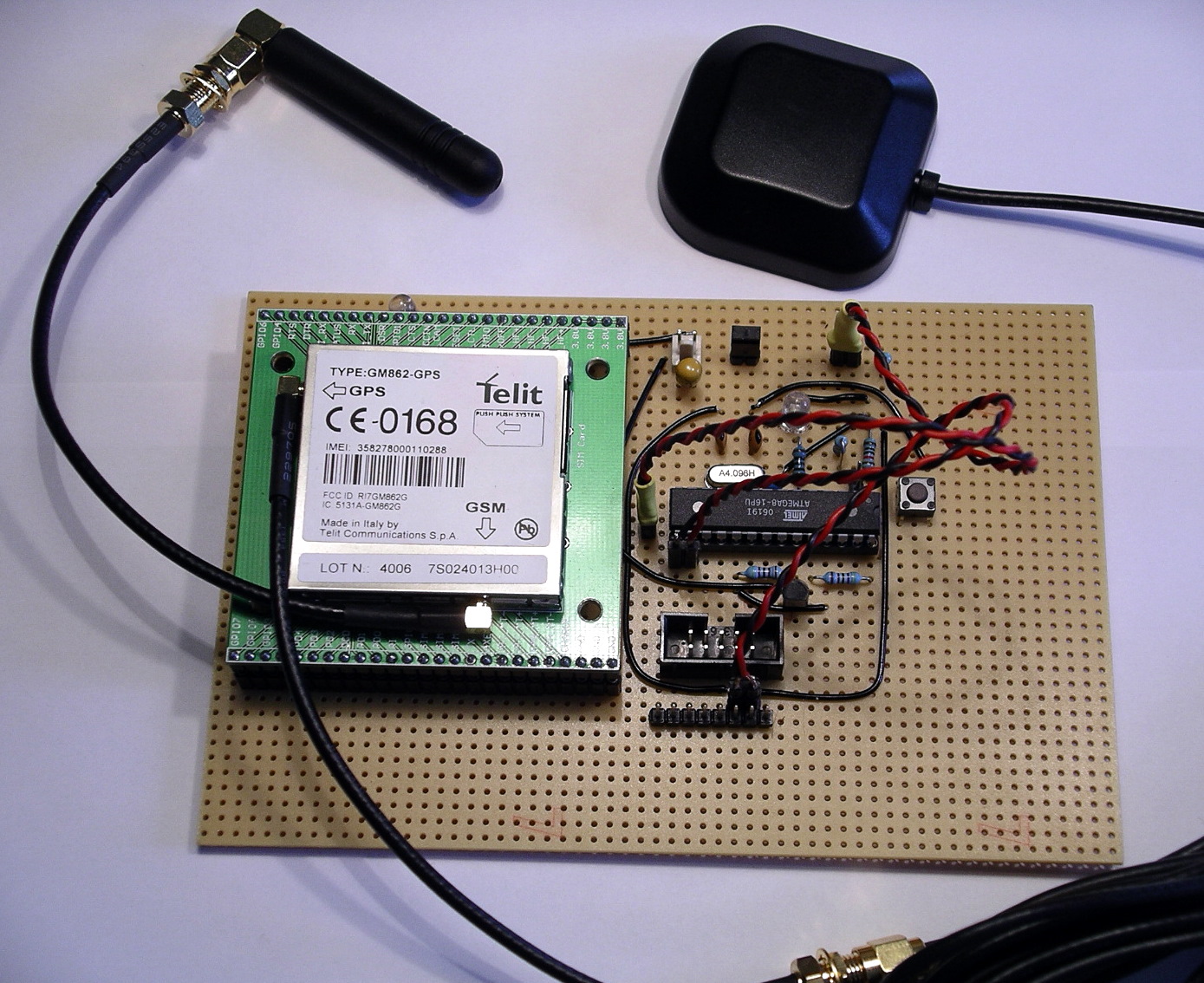
Circuit
Looking at the specs for the GM862, you realize, that it is more complex as you might have thought. A problem for me, still a beginner in electronics, were the different voltages used for the module. The power supply has to be 3.4-4.2V. Thats ok as an AVR can run on that voltage. But the serial port requires lower levels, 2.8V (CMOS). That means, you can not connect the UART of the controller directly to the module. You have to do some level translation. Fortunately this has already been solved over at Trackbox2.
Another point to mention is the power supply itself. It requires at least 2A for peaks. I used a LiPoly rechargable battery, which perfectly fits my needs. If you have to use 5V supply, you will have to use a capable voltage regulator and you have to deal with the CMOS voltage level issue as well.
![]()
As you can see, there are very few connections really required to the GM862. You have to connect the following on the breakout board:
- RX, seriell modem communication
- TX, seriell modem communication
- RTS to ground, no handshake is used.
- Status LED
- On/off to power on the module
- VCC and GND
Please keep in mind, that this is not an enterprise grade and production like circuit, so read any spec and guide before you assemble your components. You have been warned.
Operation
For now I am able to switch the module on and off, send text SMS through the module and fetch GPS positions from it. Here is an example GPS response:
Request GPS
AT$GPSACP got: AT$GPSACP
GPSACP: 131924.999,5333.9291N,00954.8841E,2.6,34.0,3,29.78,0.32,0.17,130707,07
OK
So now you know where I am living ;)
Conclusion
That’s it so far. It cost me quite some energy and money but was worth it. Next time more on software and how to talk to the GSM module.

Links
- Part Two:Using Google Maps with a Mobile GPS Tracker
- Trackbox2, great information about interfacing an AVR to a GM862, helped me a lot. In german.
- Portable Rotary Cellular Phone, tutorial at Sparkfun on how to use a GM862. There is also a forum, that has informations about GSM and GPS.
- roundsolutions.de, retailer for the GM862 with a great forum.
- Telit, all specs and guides for the GM862.
Downloads
- Eagle schematics: beacon.zip
- Eagle schematics as png: beacon.png

Nice project, I was thinking of doing the same thing with an old gps and a gsm modem. (Same as the Trackbox by the looks of it) I was looking at the ATmega128 due to the two serial ports, but seems like overkill. Only just started looking at AVR and yet to get my hands dirty, could you use a AT2313 which seem quite popular?
LikeLike
The ATtiny2313 is maybe a bit limitted (2k flash, 128 bytes SRAM). I am using the ATmega8 (8k flash, 1k SRAM) which is sufficient until now. Communication is done with a hardware and a software serial port. One is attached to the modem, the other, for debugging and monitoring is attached to my PC, so you don’t have to have 2 hardware UARTs.
LikeLike
For your serial IO, you could step down the voltage for TXD with 2 diodes (0.6V drop per diode) instead of the resistor divider it appears you’ve done. And you wouldn’t need anything at all for RXD if the output is true 2.2V since that reads as logic high for most 3.3V inputs. However, I can’t read the schem very well because the labels are too small so I’m guessing at what you did.
LikeLike
You don’t need a uController, the Telit module has Python built-in.
This is what you need to do:
1) Insert a SIM card
2) Write a python script to get the GPS position
3) setup the module to boot the python script (AT#ESCRIPT = “gps_sms.py”)
3) send the GPS position via SMS through the python script
I did this last week with the same module for another purpose. ;)
All you really need for this circuit is a power supply / charger
LikeLike
It is worth noting that the GM862 has an embedded charging circuit (for details see http://www.telit.co.it/data/uploads_EN/products/80272st10019a_GM862_Product_Description_r5.pdf page 16) although I have not used it myself.
Using embedded Python would save the extra cost / complexity of a separate microcontroller. However developing using Python can be tricky (no easy debugging capability) – the only reliable way seems to be to use the Python Debugger add-on hardware module from Round Solutions (which is not cheap). Also Python does not include support for floats, and only has the following modules: imp, marshal, md5, sys (no math etc).
LikeLike
Thanks for the input.
@Nick: Using the embedded Python is really an option. I have to check that and maybe drop the micro.
LikeLike
Are there any costs associated with GSM transmission? Sorry for my lack of understanding.
LikeLike
The costs are the same as if you are using your mobile phone. You have to pay the SMS that the module will send. For an SMS with a prepaid card it is about 0.20€ per SMS (in Germany). Most of all operators have special offers for SMS only usages.
LikeLike
Cool project.
For those not as ambitious:
Gumstix just announced their open “Goliath” board which also has GSM and GPS and adds analog audio, USB host port, 3D-accelerometer and is LCD ready. This board costs about the same as above but you’ll also need to add a Gumstix motherboard.
http://gumstix.com/store/catalog/product_info.php?cPath=31&products_id=194
LikeLike
This is great. This is certainly a different option than the one I’m thinking of doing. My method will be to use off the self equipment: ham radio, GPS, special radio modem (called a TNC).
Pros: easy, off the shelf system (I already have most of the pieces)
Cons: can be pricey; requires ham radio license (I have)
A key advantage of this system is the integration with web-based mapping. I imagine this can be done with your system as well, though.
Good going. Great idea and very educational!
LikeLike
So you basically went out and bought a prepaid gsm plan(phone) to
provide the account to send the test messages over? Pretty Slick.
LikeLike
ps. Mind posting up a pic of the underside of your board? I want to critique your soldering skills ;)
LikeLike
I’ve just bought one ready made from Fashioncar for about $270, i bet they use one of these controllers, the plus is – it’s ready built and programmed and it comes with way more extras, the bad is you still need to know in detail how it works inside as the manual is so bad that it needs deconstructing to be able to use it… :)
LikeLike
Or just use mologogo, which is about $50 total, not including service charges.
LikeLike
What would you charge to build one and send it to the US. Of course payment would be by cold hard US dollars.
Thanks,
John
LikeLike
Another $200 ready made solution :
http://www.semsons.com/ha60gptr.html
LikeLike
I was wondering if you could post a larger picture of your schematic. Thanks.
LikeLike
@John, I am not into production right now, still prototyping. It will take some months at least, as I am doing this in my spare time.
@Chris, please have a look at the full size version: http://www.zooomr.com/z/photos/zoom/2686902/size-16/
If this is not enough, I will post the eagle file in the next part.
LikeLike
This is great but what software are we using to view this info.google maps?
LikeLike
Dear Alex
i’ll be using the same module in couple of wks from now, but this time i’ll be interfacing it with a PIC microcontroller (i’m very good in using PIC’s) cos as Nick pointed out, python has no support for math routines; so the controller will handle that. But i need ur schematic as guidance but its very small on the page! Pls could u send me the eagle file? Thanks
LikeLike
@Sammy, I added the eagle schematics, please try and drop me an email if something is missing (alex [at] tinkerlog [.] com).
LikeLike
Hi,
I’ve seen this project. It’s amazing, but I have some questions.
I have bough a Siemens MC35i Termina, which can use both GSM and GPS. But the problem is that I don’t have a Software for tracking.
Can someone please help me.
Regards,
LikeLike
alex, can u emel me detail about this project. i mean the progrm, the connection and etc. i want to try it. pleaz.tq
LikeLike
hiii i like ur project iam planning to do one project like this . onething i want to know wether i can use PIC instead of using AVR controller and wat software u used to access google maps how it done
LikeLike
Hi thomas,
sure, you can use a PIC instead of an AVR. But your are on your own to migrate the code to the PIC, which should not be a real problem.
Google Maps is not accessed directly. The module sends an SMS with a link to Google Maps to your email address. If you open the email and click the link, Google Maps will open and show your position.
BTW: I am currently working on a Python version, which looks quite good so far, sending of SMS works already. Next thing is using GPRS instead of SMS. Using the built-in Python makes the external controller obsolete.
LikeLike
hi Alex, can u send me the complete code and presentation of this project plz
Also, how it work tell me the detail about it
LikeLike
Hi numan,
please have a look at part II on the link section. That leads you to part III which includes also the code and the schematics.
LikeLike
hi
nice project!
how much does a very basic gps receiver cost? is it possible to make a gps + gps module for
LikeLike
Hello Alex,
I hope that u can give me suggestion and how to… I wish to have this unit be able to connect directly to car battery…..as primary power and also the back up battery in case the car battery is loss…..
Thank you very much
Ma, Suchin
LikeLike
Hi Suchin,
scroll a bit up and look at the solution at Digital DawgPound. It uses a car battery.
Cheers,
Alex
LikeLike
Quiet a nice circuit, but in my opinion somehow to expensive. I’m still looking for a very simple AVR-based GPS Tracker with GPLed sources.
If someone finds one, please add to http://www.avr-projects.info
regards,
J³
LikeLike
Dear Alex… what crystal Oscillator are you using?
LikeLike
Al, I use a 4.096 MHz crystal.
Cheers,
Alex
LikeLike
HI ALex,
GReat job! And very cool.
I am trying to setup a Telit module myself and I have contacted them in the US. They mentioned there is a $25k PTCRB fee to get certified and on the network… How did you get past this?
Thanks
Breizo
LikeLike
Hi Breizo,
if I understood that correctly, the manufactures may certify their devices, but don’t have to. As I live in Germany, it was not a problem to get the module running.
Others in the US had no problem as well, e.g. http://www.sparkfun.com/commerce/present.php?p=Port-O-Rotary
I don’t think that this is a problem, if you want to build your own device.
Cheers,
Alex
LikeLike
I’m a complete noob and I need help..
I am trying to make an sms remote controller based on ATtiny2313 with an ericsson t10s cellphone. I cant find a feedback circuit that would confirm the status of the controlled devices via sms. Any help would be appreciated..
LikeLike
I would really like to buy one of these from you. Please email me if you want to sell it.
LikeLike
seems to me it would be cheaper to buy one all put together, but I guess that not the point.
LikeLike