Thinking up robots and machines is one of my number one pleasures. Being able to realize them, tops everything. I added a couple of power tools to my small shop and as a result, my projects got bigger and more mechanical.
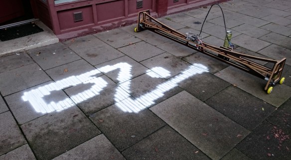
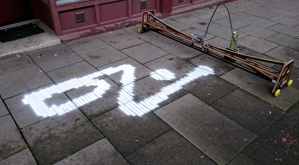
Here is my latest creature, the Paint Machine. It’s a machine the prints simple bitmaps with spray chalk on the street or sidewalk.
Some of the key features:
- dimension: width: 220cm, length: 38cm, height: 24cm, weight: 12kg
- printing speed: ca. 0.036 km/h
- resolution (4:3): 61px * 46px, print: 225cm * 170cm
- swappable print head
- remote controlled with smartphone app
I started working on this in April and built almost everything from scratch. A lot of time went in designing parts, trying them out and then re-designing them. Now I guess, it would require a lot less time to build a second one.
Needed parts and materials
Here is a list of parts that I used to build it. I’ve probably forgotten some but I think the most important ones are included. Cost for everything is around 600€ but you could definitely save a lot by using used parts or adapt to what you have already laying around.
Motors, wheels and pulleys:
- 4 inline skate wheels with bearings and spacers
- 3 Pololu 50:1 Metal gearmotor
- 4 HTD pulleys, 26 teeth
- 2 HTD pulleys, 14 teeth
- 1 HTD pulley, 18 teeth
- 2 HTD toothed belts, 160 teeth
- HTD toothed belt, 2m
Rails:
- 5 1m V-slot 2020
- 4 OpenBuilds Solid V Wheel Kits and 2 eccentric spacers
- various OpenBuilds M5 screws, T-nuts and joining strip plates
- 2 micro switches
Main body:
- 18mm birch plywood, laminated, 200cm * 40cm and 80cm * 40cm, called “Siebdruckplatte” in german.
- some wood screws
- wood glue
Electronics:
- Arduino Due
- Arduino Mega Proto board
- 3 Pololu DRV8801 DC motor driver
- 2 Adafruit alphanumeric displays
- Adafruit Huzzah ESP8266
- IRL2203N N-channel MOSFET
- 12V solenoid
- LiPo battery, 11.1V, 3600mAh
Building the main body
If you want to build your very own paint machine, plans and software are available in the links section. I’ll experiment a bit and don’t have thousands of pictures like I have in my other builds, but a couple of videos that document how I’ve built the machine. It’s not a super detailed step by step instruction but I think you get the idea. I used a variety of tools here but I’m sure you could come along with a jig saw, a drill press and a couple of hand tools.
Wheels
Print Head
The print head consists of two parts, the carriage with the motor and the real print head. That means it is relatively easy to swap the print head with the spray can for some other print head.
Electronics
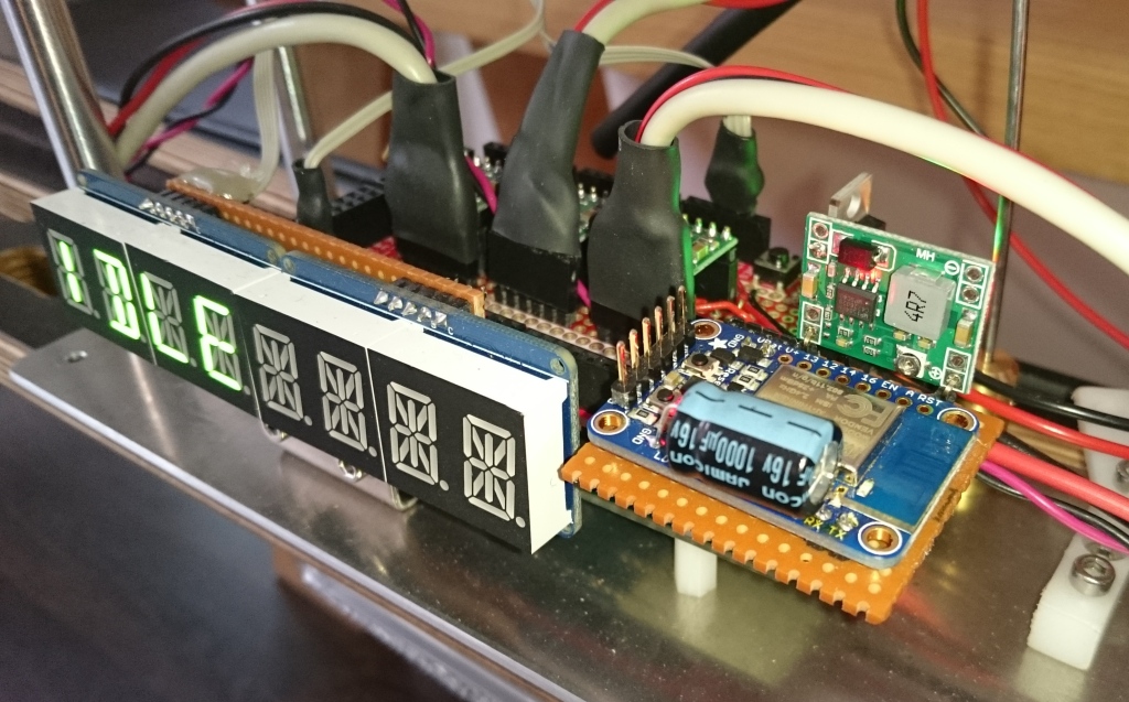
For the main board I chose an Arduino Due, that I had laying around for a long time. The Due is a 32-bit controller, running at 84 MHz, so it’s quite fast and it has a lots of pins for IO.
All extensions are soldered on an Arduino Mega Prototyping shield. The three DC motors are powered by a small DC motor driver, the Pololu DRV8801. This driver can handle 8V-36V and up to 1A continuous (2.8A peak). Every motor driver needs a PWM signal to control the speed and one pin to control the direction.
The motors have an encoder attached to its axle. The encoder generates 64 ticks per revolution. The encoder uses 4 wires, Vcc, GND, encoder A and encoder B. Problem is, I routed the power wires for the motor parallel to the encoder lines. Everything seemed to work fine, until I finally tried to drive the motor a couple of hundred ticks in one direction and then back to the previous position. That simply didn’t work. I had to rewire all three motors, using shielded cables for the encoders. After that I couldn’t see obvious errors in the positioning any longer.
As the motors are DC motors and not steppers, positioning works quite different. I’m using a simple PID-control loop, which works OK-ish. Sometimes the motor overshoots the position and has to turn back a bit (can also be seen in the video). If I decrease the amplification a bit, the motor no longer overshoots but in other situation didn’t have enough power to reach the desired position, e.g. when printing uphill. That would result in a humming, stalled machine. A little nudge then helps. I chose the DC motors because I thought that steppers would require more power to operate, especially require current to hold a position, whereas the DC geared motors hold the position simply because of their gear reduction. Still I might try steppers, maybe in a new version.
Another problem was the power supply for the ESP8266 breakout board. When powered via the main 11.1V battery, the power regulator got extremely hot. Sometimes the wifi connection simply broke off, sometimes the board seemed to get stuck in a reset loop. To help with that, I added a switched DC-DC converter and added a 1000u cap on the 3.3V lines. The ESP8266 is much more reliable now.
Software

The Arduino firmware receives commands via the serial port from the ESP8266. There are commands that can be used to control the machine remotely, like “run left motor on speed x”. The main command is sending values for the bitmap to print. Currently one pixel is configured to be 35mm * 35mm. The complete bitmap is then (4:3, 61px * 46px).
The ESP8266 acts mainly as a WiFi-Shield. The firmware tries to be as transparent as possible. It opens a wifi access point and waits for incoming socket connections. Then it just acts as a bridge between the wifi and the serial connection.
When started, the Android app tries to connect to the wifi access point. After the connection is established, the paint machine can be driven with tank like remote controls.
To send a bitmap to the paint machine, the bitmap is selected from the gallery. Minimal image processing, like level adjustment, is possible before sending the bitmap.
Conclusion
There are a couple of improvements I want to try. As the print head can be swapped, I want to construct a couple of different print heads. I have some ideas for that and I’m already prototyping one.
A custom Arduino Mega shield with all driver chips on it would be nice. If you would be interested in a custom PCB, please let me know in the comments. Also maybe a custom enclosure for all the electronics.
For the motors, I could think of a paint machine that uses only stepper motors. Maybe that would require a bigger battery but that is not really a problem.
This was a fun built, definitely my biggest and heaviest. I enjoyed building the mechanical structure, wiring all the electronics, writing the firmware and the client app. I tried a couple of new techniques and materials. Failed a lot and learned a bit. Wood for the main structure was a good decision. It took much longer than I thought with drilling, cutting and sanding, but it was worth it. A frame completely out of aluminum profiles would work fine, but would look much colder, I think.
This machine is a conversation starter, even if it was not primarily designed as such. I haven’t printed very much, because it’s November and we’re in Hamburg, but the couple of times I was trying it out, it made some heads turn. Just after the very first print in front of our office, an elderly neighbor approached me, while I was still sitting on the sidewalk, fiddling with the machine. I was expecting a couple of harsh words about vandalism, etc.
But it went like this:
-
He: Oh, what is this?
Me: That’s a huge printer. It has just printed this here. *pointing*
He: Really? Hmm … *looks at the print* … *looks at the machine* Everything built yourself?
Me: Yep.
He: Hmm. *nodding* Tell me next time you print something. Want to see it in action.
:)
Links and downloads

- github repository with source code and plans
- More hi-res pictures on Flickr
- Oz was a famous sprayer here in Hamburg


Hektor on the ground! Bravo!
LikeLike
Great concept!
LikeLike
Congratulations! The print quality is better than I would have expected.
LikeLike
Nice Project. I also had some ideas for a “chalk printing device” aka paint-machine a while ago while watching our romba cleaning robot. May I ask, why you have choosen to take the frame body approach? Isn´t it simpler to create a (much smaller) vehicle for the print head only?
As you can see, this was my first idea. But I never did more than “think” about it. So full respect for your approach and for the working machine
LikeLike
That is possible but more challenging. If you think about it, my machine needs to drive two motors exactly parallel in X direction. The movement in Y direction is fixed to the rails.
For a roomba like device to work, it has to travel a great distance in Y direction, then turn 90°, go a small distance in X direction, turn again 90° and so on. Every tiny error in one step adds up, e.g. small errors in turning will have amplified errors on long axis.
The position of the robot or machine is not absolute. It doesn’t “know” where it is. So it counts its own movement and if one wheel slips, the machine is not on the position, it thinks it is.
Hope that makes sense.
LikeLike
Hi Alex, great work! I like especially the use and the design of the multiplex-boards. Considering the possible use of stepper-motors i want to point you towards the possibility to make use of the so called powerlolu-drivers, which are also an open-hardware-design that allows you to drive stepper-motors up to 10A by a RAMPS-compatible driver, gaining a huge amount of torque. I have used them in my “bohrautomat”, see http://wiki.opensourceecology.de/Bohrautomat . By connecting the powerlolu-drivers to the z-axis-port of the RAMPS, ist easily possible to drive the two motors for the heavy gantry exactly parallel, like you stated in the comment above. By appropriate dimensioning of the motors any loss of steps doesn’t occur and therefore seems to be no problem (otherwise one could implement a simple feedback-loop mechanism, but im not sure whether this would really be necessary). Best regards, Oliver (from OpenSourceEcology Germany)
LikeLike
Thanks Oliver, I’ll check those drivers.
LikeLike
marvelous! what about the cans upsidedown? they have to be more or less “always” full to work, right?
LikeLike
These are “special” spray cans, that only work upside down, e.g. http://www.amazon.de/SparVar-Kreidespray-%C3%9Cberkopfd%C3%BCse-leuchtrot-6001029/dp/B00AFVC3ZO/ref=sr_1_4?
LikeLike
Great project! And thank you for sharing plans and code. However it could be nice to get some more details about the spray head and how you designed the things around the solenoide and the metal piece acting on the spray can?
LikeLike
I updated the sketchup model on github to include the print head and added a couple of close ups to the flickr album. Hope that makes it clearer.
LikeLiked by 1 person