

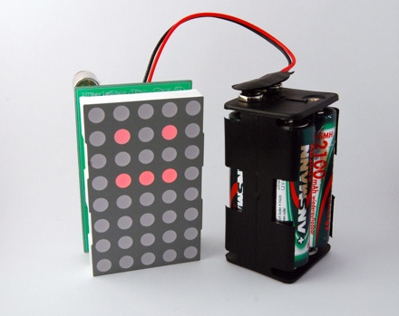
This is a new version of my Tengu clone. This time on a printed circuit board (PCB). I have them produced by Olimex and I am very pleased with the quality. The PCB worked on the first try and has some minor issues only.
Materials
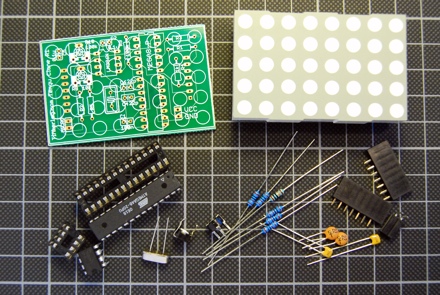
- Tengu PCB
- Everlight 8*5 LED dot matrix
- ATmega48, 4kB Flash RAM, 512 bytes RAM
- 4 MHz crystal
- LM386 Op-Amp
- 28 pin header
- 8 pin header
- 2 * 22pF capacitors
- 3 * 100nF capacitors
- 10k potentiometer
- 100k potentiometer
- 100k resistor
- 5 * 1k resistors
- 2 * 7 pin header sockets
- 2 pin headers for power supply and microphone (optional)
- Electret microphone (not on the picture)
Note, that the electret microphone has a polarity. On the PCB the inner pin is the positive one. If you connect it the wrong way, it is heating up really quick.
The microphone that I used here has an impedance of 2k. You may have to experiement a bit with different microphones.
The capacitor C2 is used to control the amplification of the LM386. I used 0.1uF but you can use up to 10uF to get a stronger amplification. Here is the amplifier circuit that I used.
PCB design issues
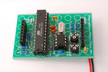
As this is my first design, there are a couple of things that I would redesign.
As I tried to insert the pin header sockets, I realized that the drill holes were a bit too narrow. You have to use a bit of strength to insert the headers, but it works.
All solder pads used for resistors and capacitors are a bit too small. It was a bit difficult to solder them. I would make them a larger next time.
I think I should use a bit less of the silk layer. Some solder pads are covered with silk. Most of the time that does not hurt as it is on the top side. But there are pins that you may wont to solder on the top side, e.g. the power connector.
Improvements
The component count could be reduced if I had dropped crystal. For the animation of the LED matrix the internal oscillator would be sufficient. On the other hand, with a suited crystal, this circuit could be modified to display the time.
I would add an ISP (in system programming) header for easier programming. Now you have to flip off the display, take out the controller, program it, re-insert it and put the display back in place. Not a fast turn around if you want to modify the firmware.
What would you think of an Arduino version of this circuit? The controller could be replaced with an Arduino compatible ATmega168. Or maybe as an Arduino shield?
Conclusion
It is great to see your first produced PCB. Even better if it works on the first try. Maybe I can even build a kit out of it with the next revision of the board.
As I have still two boards left, you can email me at alex at this domain and I will send you the PCB for free. The only requirement would be, that you really want to build it and that you give me feedback on how it worked, what you would change or how you modded it.
Links and Downloads
- Crispin Jones Tengu, the original idea of this device
- Mini Amplifier with LM386
- Tengu clone on prototype board
- Tengu clone on a breadboard
- tengu cloneSource and Eagle schematics
- More at Flickr.

Hi Alex,I am from Greece if you want send me pcb.
Dimos Apostolidis
veranzerou 34 10432 ATHENS GREECE.
Thanks.
Dimos
LikeLike
Alex,
Thanks for the update. The board looks amazing. I’m interested in a PCB, but lately have been unable to put time into my EE hobby. I cant wait for the kit.
When I tried mine on the breadboard + arduino, the microphone I used was not very sensitive and so it didn’t work as well as I would have hoped.
I think an Arduino Shield is a good idea, but the tengu looks really cool as a the small package it is now (besides the battery pack). Although, it is more convenient for those who already own an Arduino, like myself. This project makes a good first soldering lesson–it doesnt have any surface-mount.
The addition of the ISP sounds likea good idea, that would probably the best improvement.
It was exciting to see this project evolve from the breadboard to the protoboard, and now to the PCB.
Cheers,
David
LikeLike
Ok, the two boards are gone. I’ll let you know when the next revision is ready.
Cheers,
Alex
LikeLike
Thanks Alex!
LikeLike
Does anyone have a link to an online store that stocks all of these parts. I’m having trouble finding the led dot matrix. any help would be appreciated.
LikeLike
hey. great work. i was curious: how much is a PCB like that when you get it from olimex?
i was in the process of designing the same thing (for another application) but with the connectors for the display on the back of the PCB. and built arounf the 168.
your work looks great though. congrats.
LikeLike
tateu,
That depends. If I look at my order, I would say a tengu board cost around 8 or 9 Euro. That is not really cheap but can get lower if I order in bigger quantities.
Cheers,
Alex
LikeLike
Oh I would love one, that is if yo have any left. He would be totally fun!
Nice project!
Lee
LikeLike
I would definatly reccomend going for an arduino and 168. This would not only allow the kit to be easily modified and programmed(a la http://www.moderndevice.com BBB), but it would also allow people to build their own with an arduino that they already own.
LikeLike
@Lee, I am sorry, but I had only two and there are gone already.
@Kersny, BBB is a good option but I am not sure, if a complete BBB would fit underneath the display. Maybe an ATmega168, so you can at least program it like an Arduino.
LikeLike
I have had the same problems with Olimex. They don’t process the silk screen layer and mask off from the soldermask. You end up with silk all over surface mount pads. — bad
LikeLike
Yes, I noticed that on my boards. I thought, I was to blame for that.
LikeLike
Here is a link to a german online shop for the everlight 5*8 dot matrix.
http://www.conrad.de/goto.php?artikel=156379
LikeLike
Wow, very cool! If you had a kit with preprogrammed MCU, I’d so buy one!
An arduino version would be cool too, but I really like this design because the whole thing fits in the shadow of the LED matrix. Plus, if you wanted to install this in something, there goes your arduino board.
I might have missed this in the post, but do the pots change the volume sensitivity? That would be really useful so you get the best range of facial motions for the sound levels present.
Thanks for sharing this!
LikeLike
Kevin,
yes, the pots control the volume and the sensivity of the op-amp.
Cheers,
Alex
LikeLike
I love the design. Like Kevin said, an Arduino shield would be great, but there is something about the form factor of everything fitting behind the LED matrix.
Count me in for a kit, if you decide to put one together.
LikeLike
http://www.pollin.de/shop/detail.php?pg=OA==&a=NzQ4OTc4OTk=&w=OTg4OTk4&ts=0
for the guys from germany .. a cheaper 5x8matrix. less then a half of the conrad price.
LikeLike
RBT,
many thanks for the link. I was already searching for cheaper source for the display but missed that one. That will reduce the overall cost. Great.
Cheers,
Alex
LikeLike
Great job! I actually built one of these myself with an AVR and an 8×8 matrix. They are a lot of fun :)
I just have one question; according to the video, you use a Mac. Do you design the PCBs on your Mac? If so, what software do you use? Lack of decent PCB software is the only thing stopping me from buying one.
LikeLiked by 1 person
Hi Jeremy,
yes, I am using Eagle CAD on my Mac. They have a limited but free version.
http://www.cadsoftusa.com/download.htm
Cheers,
Alex
LikeLike
Hi Alex, I need .hex please.
LikeLike
Hi dimos,
I updated the zip file. Please check it out.
Cheers,
Alex
LikeLike
Hi Alex,
I’m Dimos friend, and we try toggether to make it work.
Thanks for the Hex update, but can you tell me the fuse settings? For some reason, it doesn’t work even if I set the fuses to correct ones for the 4Mhz crystal.
I use AVR Studio4 and STK500 to program it!
Best Regards, Thanos
LikeLike
Hi Thanos,
the fuse settings are: low 0xCD, high 0xDF.
Cheers,
Alex
LikeLike
Hi Alex,
I set the fuses as you said but still no luck…
I noticed that Dimos had used the ATmega48V-10PI that is low power version of the ATmega48. I believe its the same thing, right?
Another thing that might be the reason that this isn’t working could be the 8*5 led matrix… The one we have is the Kingbright TA24-11EWA (N) (other codes: 97-12). I believe is (A)node driven. Yours is (K)athode driven?
The problem is that we can see all the leds light dimly. And no reaction to sound.
Regards, Thanos
LikeLike
Hi Thanos,
looking at the Kingbright datasheet, it has a common kathode per row. The Everlight (ELM-2081SURWA/S530-A3) has a common anode per row. So try to get another dot matrix or invert the outputs of the controller.
Cheers,
Alex
LikeLike
Hi! Could you tell me how you connected the electret to the arduino board? Is it enough to connect the electret mike to the board to give arduino the input of the sounds detected by the mike?
I am going to use it to make leds light up, and the leds are doing ok, just I don’t know how to make it all work (hardware) with a mike.
Thanks really, I have been sweating on this a while
Mariadele
LikeLike
Hi mariadele,
you can not connect the mic directly to the controller, the signal is too small. I used the LM386, an OP-AMP, to amplify the signal.
Here is the link, where you can see, how to assemble the mic, the LM386 and the controller.
https://tinkerlog.com/2007/10/22/diy-tengu-on-a-breadboard/
Another mic with amplifier that I found lately looks very promissing. It’s made by the guys from Sparkfun.
http://www.sparkfun.com/commerce/product_info.php?products_id=8669
Cheers,
Alex
LikeLike
Funny… was looking over your stuff and noticed I had some 5 x 7 matrix displays laying around… and an arduino…
I might try to replicate this onto my own MCB as an Arduino Shield possibly… would make it quite unique…
LikeLike
hi Alex,
Cool…. is a very interesting project. I might want to try it too..but izzit possible for me to get the PCB board?
thanks.
LikeLike
Hi motorbuddy,
sorry, all PCBs are already gone.
Cheers,
Alex
LikeLike
Hi Alex, look this: http://www.grobot.gr/index.php?option=com_content&view=article&id=104:-by-alex&catid=43:2008-04-19-14-02-08&Itemid=82
My new web site
http://www.grobot.gr
LikeLike
dimos,
great, you did it! And the video is cool.
Thanks for sharing it.
Cheers,
Alex
LikeLike
Hello Alex, Great gadget you have there, Have you got any new PCB’s I need two of them and I don’t know if you can provide all the parts as a kit? Is that possible?
Thank you.
LikeLike
manos,
sorry, I don’t have any new PCBs and I won’t do any new ones. But you can take the Eagle files and do it on your own.
Cheers,
Alex
LikeLike
Hello!
I have question about ISP, how create it? where to connect?
Maybe you can give me some link?
Thank you!
LikeLike
If you are completely new to AVR programming, then take a look at instructables, they have great tutorials on that.
LikeLike