This is Mechpen, my newest drawbot.
The idea was to have a robot arm that could sketch on a rather large surface.
It is a SCARA (Selective Compliance Assembly Robot Arm) robot arm, meaning the robot has a shoulder and an elbow joint and a hand. Mechpen has a reach of 140 cm which means it could sketch up to A0 format.
Hardware
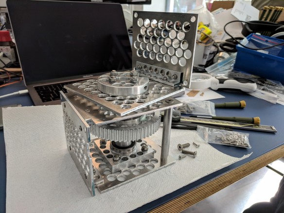
Most self-built SCARA robots you find online are used for 3D-printing and have a rather limited range but good accuracy. Mechpen in contrast was designed to have a long range while still have ok-ish precision. So the arm and everything that reaches out from the base should be as light weight as possible. It don’t has to carry more than a pen. Both motors and all the electronics have to sit in the base structure. The base structure can and should be heavy, so it doesn’t tip over if the arm is fully extended. All in all Mechpen weighs around 15 kg.
I bought the pulleys, bearings, belts and that kind of stuff. The rest of the hardware was custom machined. I even drilled a lots of holes in almost every part of the arm to save some weight.
Each part of the arm has a length of around 700 mm and is built from 6 mm carbon tubes. Each tube is slightly angled inwards in the forward direction. This alone was not enough, the upper arm twisted quite a bit when the forearm was at 90°, so I added two more diagonal tubes to the upper arm. That helped a lot, but even that did not solve the problem completely. More on that later.
The motors have a 0.9° step, which means 400 steps for a full circle. Each motor is geared down with belts by factor 5. With the drivers set to 1/32th stepping that makes 177.778 steps per degree.
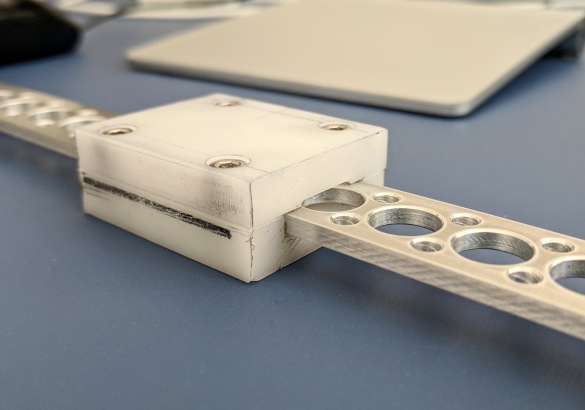
Initially I wanted to have the possibility to rotate the hand with attached tools or pens. That plan was dropped because too complicated (and not needed for pens). The easier version was a servo that could lift the pen. As I wanted to lift the pen more than just a few mm, I designed a linear rail and a wheel that is attached to the servo. Then there is a nylon wire attached to both ends of the rail and with a 180° servo I could get a travel of around 70mm max.
At the bottom end of the rail I attached a small piece of Delrin in which I inserted two small magnets. For the pen I machined a spring loaded mechanism, which also has two small magnets and snaps perfectly into place when it comes close to the rail. This way I can swap out pens easily or even replace it with a sensor.
Some of the machining can be seen in the Making of.
Electronics
Mechpen’s brain consists of a Einsy RAMBo board and a Raspberry Pi. The Einsy RAMBo is a board designed for 3d printers, e.g. it runs in the latest and very successful Prusa MK3 printer. It uses TMC2130 driver chips from Trinamic to control two NEMA 23 stepper motors (0.9°). These chips have a couple of smart features that make them almost silent and very current efficient.
The Raspi runs a high level printer management software, named Octoprint, that talks to the Einsy RAMBo via USB-cable. Both boards are powered by a 12V 35W notebook power supply.
To make the pen lifting mechanism as light as possible I thought of a bowden wire, driven by another stepper motor, that sits in the base structure. This turned out to get more and more complicated. Therefore I looked for a small and light servo with much travel as possible. I found the TGY-180D from Hobbyking, which is one of the very rare small 180° servos. It’s cheap, a bit noisy but works quite ok until now.
After the first tests I found out that the elbow still flexes too much to get good results. The hand was about 20 to 25 mm lower if the elbow was at a 90° angle. That could not be covered even if the pen was spring loaded. The drawings were distorted in one place and the pen wouldn’t even touch the paper in other places.
OK, then use software to fix a hardware problem (most of the times a bad idea)! First I measured the difference in all angles and it looked as if I could get away with a sin function, depending on the angle between upper arm and forearm. Unfortunately that didn’t really work out.
That next idea was to use, what is known to 3d printers as bed levelling. I bought a VL6180X distance sensor and attached it to the lifting mechanism. With that I could scan over the whole plotting area and record the height at multiple points and build a grid of height values. Using this information I could adjust the height accordingly, while plotting. Bonus is that plotting even works if the ground is a bit uneven. The accuracy in height is good enough for my purpose so it looks like I get away with it this time.
Software
On the RAMbo board runs a tweaked version of Marlin, a firmware for 3d printers. The firmware accepts G-code as a way to control the printer. Marlin supports a variety of different 3d printer configuration but unfortunately the support for SCARA kind of robot arms is broken right now. A couple of forks exist but nothing was working for me. Also, if you’ve looked into the Marlin source once, it’s quite gigantic and takes a while to get familiar with.
I wrote a small SCARA simulation in processing to get the forward and inverse kinematics right. After I got that working, I tweaked my Marlin version and implemented the missing parts. It took a while but finally the robot behaved. Currently Mechpen only draws in the first quadrant, so from 0° to 90°. This could be extended to make it draw also on the fourth quadrant, to -90°. I left that out right now because it non-trivial to implement and optimize.
I added additional G-code commands to control the servo to lift the pen. Marlin had already servo support integrated but without any easing, so the arm was heavily shaking up and down after a pen up or pen down command. I replaced the servo lib with Todbot’s ServoEaser, which works much better.
To support the bed levelling I added another gcode command to trigger the recording. It moves the sensor to all positions of a grid and takes several measurements and saves the average. After it’s done with all points we can save the data to EPROM to have it available, even after a reboot.
On the Raspi runs Octopi, a preconfigured version of Octoprint. This great piece of software (all open source!) is normally used to control and manage your 3d printer over the local network, without the need to have your main computer attached to the printer while printing. And because of that I can upload my gcode files via WIFI to Octoprint on the Raspi and then use the web UI to start or stop a plot job. I can even flash the Marlin firmware over WIFI. Nice!
No customizations on this part.
To convert line graphics (SVG) to G-code I wrote another tool in processing, also named Mechpen. With it I can load SVG files, scale them and move them to correct position for the plot, to be sure everything fits on the paper. Additionally I can select how every path is plotted (hide, stroke, hatch-fill, stroke and hatch-fill). This enables me to do multi color plots. I load the SVG, enable all paths for one color, export it to gcode, then do the next paths of the other color and export it again. So I end up with a two or more gcode files. Then all gets uploaded and the first plot is started. After it is finished, I can change the pen for another color and start the next gcode file.
To get input for the plot we have different options.
To plot a picture, I usually select a photo and the use inkscape to convert it to vectors. It helps to reduce colors to 3, max 4 colors or grays. Then this SVG can be used in Mechpen to create paths with different hatch fills, depending on the color or gray value.
To plot a drawing, e.g. a patent drawing, I load the bitmap in inkscape and select “centerline trace”. That’s an extension, here on github.
Another great option is to look for nice plots on Turtletoy. Turtletoy lets you explore turtle graphics with only a couple lines of javascript, e.g. the plot above is called Cubic cityscape. Every turtle can be exported as SVG.
A further option is to do some coding in Processing. Doing line graphics and exporting it to SVG is extremely easy in Processing. Two examples are included in my Github repo .
For inspiration, follow #plottertwitter on twitter.
A nice collection of tools, resources etc. can be found on drawingbots.net.
Wrap-up
This project took a while to complete, almost 16 months of my spare time, on and off.
The accuracy is within a couple of millimeters, if all belts and set screws on the pulleys are tight. There is a certain wiggling that can be seen on the plot. It’s stronger in certain areas, depending on the speed and also the angles the arms are at. In other areas it’s a clear straight line. However, for me that adds to the character of Mechpen ;)
Of course you can build robots that are more accurate, but only with stiffer and sturdier materials, which means more overall mass, which means bigger motors, which means even more overall mass.
With this machine, the finished drawing is nice, but it’s quite more interesting to see how the plot develops. It’s a bit like campfire. I like that.
Thanks to JumJum for letting me use his Tuna and the Robot!
Thanks to Jan for letting me use his Greta design!
Links
- Github repo Source and design files
- My Marlin firmware fork
- More hires images
- Einsy Rambo
- TGY-180D servo with 180° travel
- VL6180X distance sensor from Pololu
- NEMA 23 Stepper motors from Stepper Online
- Marlin, 3d printer firmware
- Octoprint
- Todbot’s ServerEaser
- inkscape extension: centerline trace
- Turtletoy, turtle graphics with Javascript
- Processing
- SCARA robot arm
- drawingbots.net


1 Comment
Comments are closed.