

Arduino is a great prototyping platform and most of you probably know already about it. If not, check out the Arduino pages and the Arduino playground and dive into it.
A couple of month ago I ordered my first Arduino board. It was one of the Diecimila revision. As I often try something on my breadboard, I found out, that it can get troublesome to connect the Arduino with the breadboard over and over again. Others found that out as well and have solutions for that. An Arduino clone that snaps nicely onto your breadboard, e.g. Boarduino or RBBB.
So what to do if these boards are far away across the ocean and it is holiday season everywhere? You may have guessed it, we build it on a prototype board.

Gather components
Luckily I had most needed components laying around. The ATmega168 is replaced by an ATmega8 but that is not a problem as the very first Arduinos were based on that chip.
- ATmega8, 16MHz, 8kB flash memory, 1kB sram memory
- 2 x 0.1u capacitors
- 2 x 22p capacitors
- 16MHz crystal
- 10k resistor
- 1k resistor
- red 3mm LED
- button
- 6 pin header for ISP
- 3 pin header for serial communication
- prototyping board
- USBtoRS232 converter
- ISP programmer
All components can be bought for about 4.50€, without the ISP programmer and the USBtoRS232 converter.
If I had a resonator, I would have taken that, instead of the crystal and the capacitors as it needs less space on the prototype board.
The USB to RS232 converter is called USB-2-bot and comes from another project. Any other converter would work as well, e.g. this USB-TTL-232-cable from adafruit.
Schematic
The schematic is mostly the same as for the Boarduino. I left out the power supply circuit. 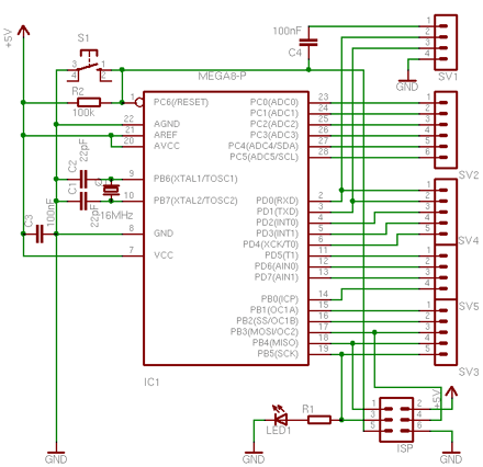
It has an ISP connector to program the bootloader and a serial connection used for uploading Arduino sketches. Also in place is a capacitor for the auto-reset function. It is connected to RTS line on pin 1 of the serial connection. The board should be feature compatible with Arduino.
On a breadboard
First you can assemble all parts on a breadboard.

Bootloader
All Arduinos are comming with an installed bootloader. If you build it yourself, you have to program the chip with a bootloader, at least once. That is why we need the ISP programmer.
First I tried to use the ADABOOT bootloader which is a modified version of the original bootloader. It has some modifications that makes it more comfortable, e.g. starts your sketch right after the upload is finished, without having to wait several seconds. Unfortunately I could not get it to work. I was able to compile it after adding some special #defines for the ATmega8. Programming it worked as well. I can see that the bootloader runs, as it blinks the LED four times, but it wont connect to the Arduino IDE. It always gets a read timeout.
So I took the bootloader that came with the Arduino IDE. It can be found at /arduino-0010/hardware/bootloaders/atmega8/ATmegaBOOT.c.
You can try to call make to compile the bootloader or take the precompiled ATmegaBOOT.hex file. I needed to adapt the DIRAVR path setting in the Makefile to make it work. I used only the compile target, so I just typed
make clean; make
That gives you a warning, that delay.h has been moved, but you can ignore that.
Fuses
Next thing is to get the fuses right. If you are new to AVR microcontrollers, these fuses
are used to configure some properties of the AVR chip, e.g. which clock to use: an
external crystal or the internal oscillator. These fuses are registers that can be programmed, just as you can program flash memory.
Programming the fuses is always fun. Every option you want to enable or disable is represented as a bit and grouped in two 8 bit values, high fuse and low fuse (for ATmega8). To make it hard to read, programmed bits are represented by zeros and unprogrammed by ones. To make it more fun, if you mix things up, you can “brick” your controller and it can get hard to revive it. And because you probably do fuse programming only once per chip, you may have forgotten most of it when you have to do it again.
Good for us, that fuse bits are provided in the Makefile that comes with the bootloader. As I use avrdude for programming, this is how my command line looks like.
avrdude -v -c usbtiny -p ATmega8 -C /Users/alex/etc/avrdude-tiny.conf -U hfuse:w:0xCA:m -U lfuse:w:0xDF:m -U lock:w:0xFF:m
This writes the high and low fuses and the lock bits. Lock bits have to be written to enable programming the bootloader.
Programming
Now we are ready to program the bootloader.
avrdude -v -u -p ATmega8 -c usbtiny -C /Users/alex/etc/avrdude-tiny.conf -U

flash:w:ATmegaBOOT.hex
When that is done, try to hit the reset button and you should see the LED at pin 13 blinking. That signals that the Arduino is ready to accept your sketch.
Testing it with an Arduino sketch
Next thing is to check if our Arduino wants to speak to the Arduino IDE.
Start your Arduino IDE and load the Blink sketch from the examples. Compile/verify it and hit the upload button.
By now, and if everything goes well, you should see the LEDs of your serial connection blinking, resetting the Arduino and the uploading the sketch.
Then your LED connected to pin 13 will blink once every two seconds.
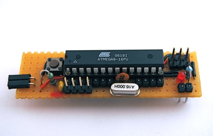
On the prototype board
If you have tested your components and your software successfully, you can move on to solder it on a prototype board.


If you solder header connectors to a prototype board and try then to connect it to the breadboard, you will notice, that the header connectors are a bit short. I used my pliers to push the pins a bit. If you solder these, you will have a better connection to the breadboard.

Conclusion
This Arduino can be used for old school prototyping as well. Just use it as a standard ATmega8 and program it with the ISP connector. And it is one of the cheapest Arduino boards, that you can get.
Links
- Arduino home
- Freeduino index for everything related to Arduino and Arduino clones.
- Boarduino Arduino for the breadboard from Adafruit Industries.
- RBBB Arduino for the breadboard from Modern Device.
- Arduino XMAS hitcounter
More at Flickr.

Very nifty.
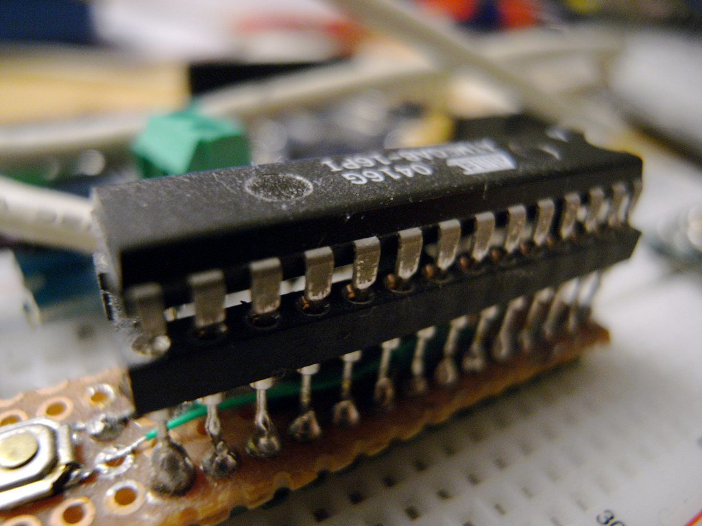
In case anyone else is looking for a view of the back of the board it’s here:
(Took me a while to find as it’s not tagged ‘prototypeboard’… :-) )
Any chance of a nice diagram of the protoboard component placement/wiring? :-)
–Phil.
LikeLike
Hi Phil,
I tagged the photo.
For the diagram of the protoboard, any suggestions for a good software for that?
Cheers,
Alex
LikeLike
This is cute one.
Good work
LikeLike
GREAT work – I’ve tried to do something like this myself, but I could never get it all together in my head. Your use of links and connections, and components under the IC itelf, it pretty damn smart.
Have printed out all the layout photos to make my own.
Thanks
Alex
LikeLike
This was my approach to a tiny DIY breadboard arduino:
Under the ATmega is the clock, on the left an smd reset switch.
LikeLike
I can’t get the auto-reset working on this. i have tried switching the attiny168 with the one from my boarduino and still nothing.
LikeLike
Tim,
have you checked if the capacitor is connected to the right line (RTS)?
Cheers,
Alex
LikeLike
If you load the unit with Simple Message System from the archives at arduino.cc, you can control it from linux with my package of shellscripts. See http://user.cavenet.com/rolandl, download SMS1.tgz. Full IO and PWM control. AD is scaled to mV and formatted for import to most spreadsheets. Now with a GUI via the xdialog command. Proof-of-concept, easy to customize for your project. Modular, can handle multiple units if needed.
I am currently controlling 12 reed relays (elexp.com #22RD5) directly from the IO pins, to control AC relays.
LikeLike
If you want to use an ATmega32 here is an easy DIY development board that will help you to develop your skills with this microcontroller: http://www.microdiy.com/index.php?/atmega/diy-atmega32-development-board.html
Have fun developing new stuff!
LikeLike
Hi Alex,
thank you for documenting your work. I was wondering how you uploaded a sketch from the Arduino IDE with the usbtinyisp to the micro. Did you setup a boards.txt file in your ~/Arduino/hardware/ directory?
I can upload sketches with the isp but, have to change the upload.using inside preferences.txt. It would be nice to switch that from the Arduino IDE Tools>Boards.
Thanks for your help.
Dominik
LikeLike
Hi Dominik,
I just programmed the bootloader by hand, haven’t tried the Arduino IDE for that.
Cheers,
Alex
LikeLike