Tinkerlog header image 2

Tinkerlog

Alex’ blog

Der Kritzler

September 2nd, 2011 · 53 Comments · Arduino

In May I moved into a new office with the great guys of The Future of Everything. The office has really nice big windows and we thought about what we could do with them. I remembered hektor, this super cool 2D drawing machine. What if that thing could draw directly onto the window?

So, here is Der Kritzler (kritzeln is german for scribble).

Parts

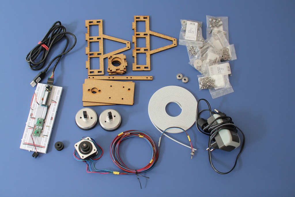
Here is a list of parts needed:

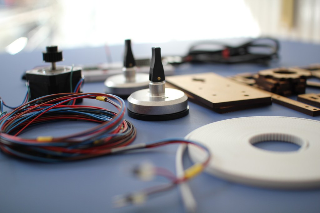
  • Motor mount and pen holder, laser cut MDF, 5mm Formulor (german partner of Ponoko)
  • 2 stepper motors, NEMA 17. e.g. Reichelt
  • 2 suction cups with mount, esska
  • Various M5 and M4 bolts, screws and washers, 2 ball bearings Screws and More
  • 2 toothed belt pulleys, Mädler
  • 6 m toothed belt, Mädler
  • Arduino or breadboard compatible Arduino clone
  • 2 stepper drivers, A4983, Pololu
  • Standard servo (missing on the photo)
  • Power supply, 3-12V, 2250 mA, conrad.de

Most sources are german, but I assume that all parts are pretty common. The toothed belt was extremely expensive, almost 20 Euro per meter and I ordered 6. There has to be a cheaper source, especially because I don’t need the best material available.

The SVG to cut the motor mount and the pen holder was my first attempt to have something laser cut. To be honest, it was my second, the first one was a complete fail. This one worked. I designed it in Inkscape because I haven’t decided yet which 2D CAD tool to use. Inkscape can be really annoying but you can get it done. The design is not optimized so it makes a lot more cuts than actually needed, which makes it more expensive.

Assembling

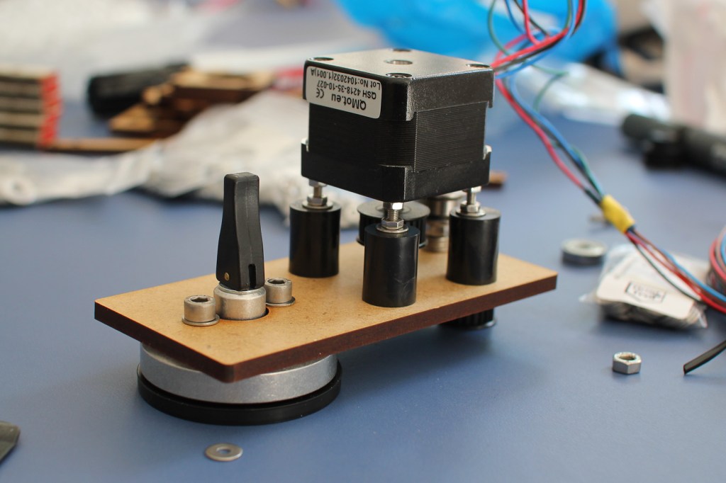
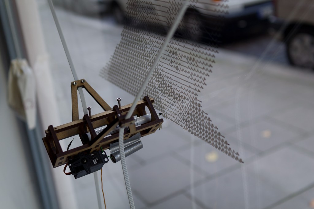
The motor is mounted with its axis towards the motor holder. That way the belt is kept as close as possible to the window. I had to use the black tubes as spacing washer, because the thread on the bolt doesn’t go up all the way. I should look closer next time at what bolts I order.

Assembling the pen holder is quite easy. I just used some wood glue to glue all parts together.

Electronics

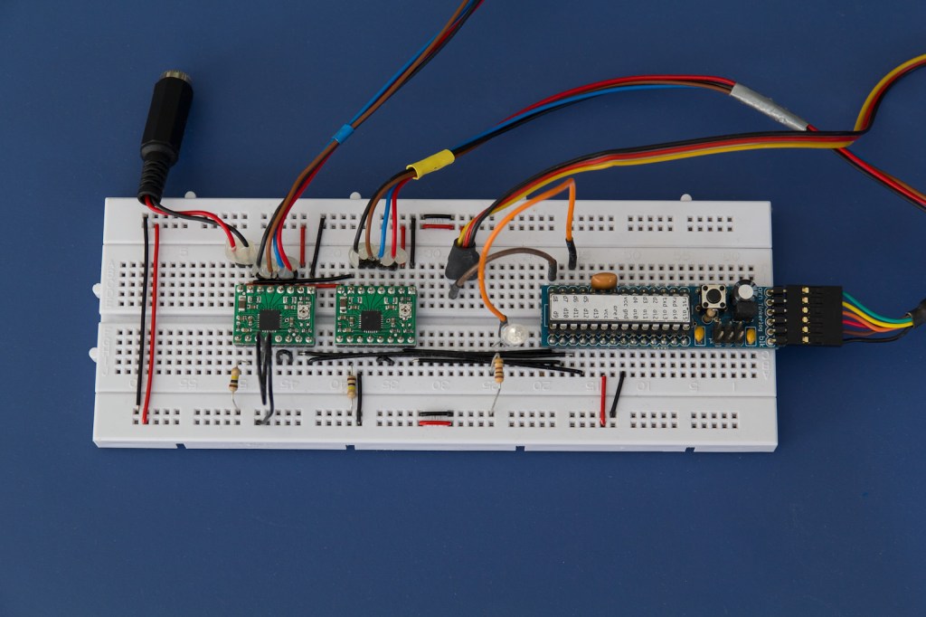
I am using the drivers with quarter stepping, which means 800 steps per revolution of the motor. The pulley has a circumference of 62.8 mm, that gives a resolution of ~0.08 mm per step which is far enough for such a device.

The driver board is connected as follows:

  • 2B – black
  • 2A – brown
  • 1A – blue
  • 1B – red
  • MS1 – GND (via 100k resistor)
  • MS2 – VCC
  • MS3 – unconnected (means low, has internal pull down resistor)
  • RESET and SLEEP are connected

The connections from the Arduino are:

  • pin 6 – Debug LED
  • pin 8 – Servo signal
  • pin 9 – Driver 1, DIR
  • pin 10 – Driver 1, STEP
  • pin 11- Driver 2, DIR
  • pin 12 – Driver 2, STEP

The firmware boots up and expects the motor mounts to be 1500 mm placed apart from each other. The pen holder is placed in the middle with 1060 mm on the timing belt to each side. That position has to be the same every time the machine is powered on because it has no feedback where the pen holder really is.

The Kritzler is then ready to receive commands from the host machine. Possible commands are:

  • m dx dy (move relative)
  • l dx dy (line relative)
  • M x y (move absolute)
  • L x y (line absolute)

For every new command it is computed how much steps had to be executed to move the pen to the new position. That involves a bit of geometry because we have to transform the position in x,y into a position that depends on the length of the two belts. If the command is a move command, the servo is used to keep the pen away from the window.

For debugging it is also possible to connect to the Kritzler via a simple terminal. Then you can examine the plotting area, for example, by simply typing M 1000 1000 into the terminal and see where the pen goes to.

Software

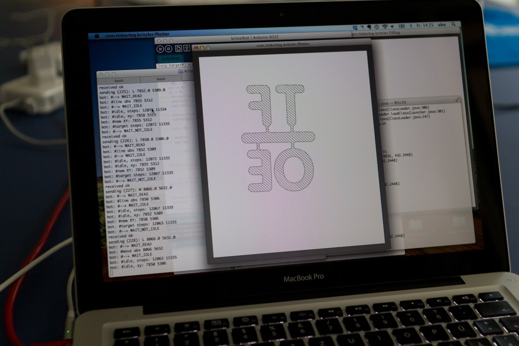
I used Processing for implementing the host software. Processing was the first choice because it is primarily targeted for graphics programming and plays well with Arduino. Any other software that could talk to the serial port would work here as well.

The host software falls into two parts. The first part is for reading an SVG file and sending it to the machine. It starts with loading the first SVG file from a directory if there is one. Then you could still scale, mirror and move the shape on your canvas. If everything fits, the drawing is sent to the Kritzler, one instruction after another.

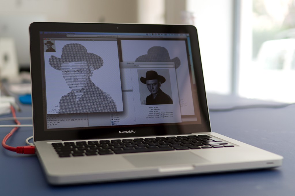
The other part is used to transform bitmaps into more or less pretty SVG files. I have two snippets at the moments. One converts a bitmap into a SVG by using some sort of halftone algorithm. It produces a horizontal line with more or less jitter, dependent on how dark the current pixel is. The second uses ImageMagick and Potrace to convert a bitmap into an b/w SVG file. That black outline is then filled with diagonal lines by another small Processing sketch.

All tools read and write files from special directories. That means tools can be somewhat chained together. One reads files, preprocesses it and stores them in a new directory. Another tool then reads that file and sends them to the Kritzler. To process the SVG files, I first used the built-in functionality of Processing. After some poking around I switched to Geomerative which is a really capable SVG library for Processing.

Testing

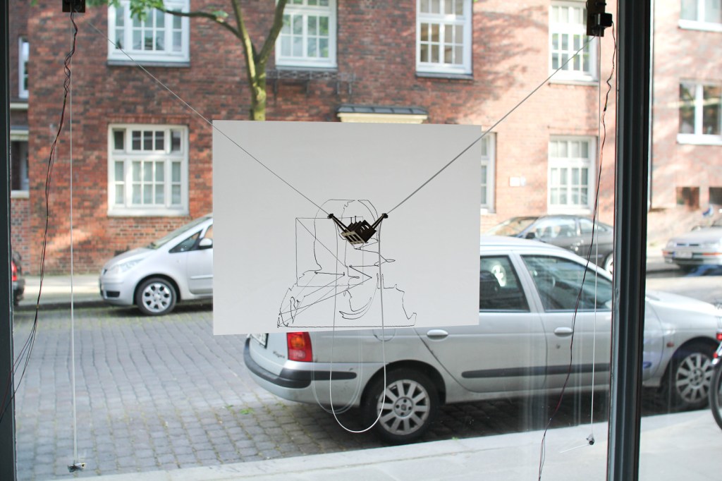
This is the very first drawing done by the machine. I used a whiteboard foil on the window which worked pretty well. The pen is a permanent marker. I tried many different pens until now. Whiteboard markers are great for drawing on the window. They could be wiped off easily but are not very intense. My favorites for drawing directly on the window are pens with liquid chalk. Although all I tried have some kind of valve to fill the head. That means you have to monitor the drawing process and when the chalk gets thin, stop the drawing to refill the head. There must be an easier way. Maybe making my own liquid chalk?

More Scribbling

Conclusion

This is my first project that uses ropes, gears and motors. The hardware could be build prettier and cheaper. Maybe I’ll build another more optimized one. We’ll see. Nevertheless I am quite pleased with the outcome. Always great to see people passing the window and then get attracted by the Kritzler, while he paints on the window.

This project is based on great software and inspired by some super cool 2D plotting devices.

Links and Downloads

53 responses so far ↓

  • 1 Arne // Sep 2, 2011 at 18:30

    Not that I understood any of this. But I’ve seen it in action. just awesome!!! Great work!

  • 2 la23ng // Sep 2, 2011 at 20:41

    Mir gefällt am besten der Minimalismus der Mechanik. Sehr toll.

  • 3 Der Kritzler – The Drawbot | tech.nocr.at // Sep 2, 2011 at 21:27

    [...] [Link to Der Kritzler] [...]

  • 4 Der Kritzler – A window draw bot… « adafruit industries blog // Sep 2, 2011 at 22:25

    [...] Der Kritzler. Alex writes – In May I moved into a new office with the great guys of The Future of Everything. The office has really nice big windows and we thought about what we could do with them. I remembered hektor, this super cool 2D drawing machine. What if that thing could draw directly onto the window? [...]

  • 5 Pete Prodoehl // Sep 2, 2011 at 22:45

    This is awesome! Building one of these is on my TO DO list…

  • 6 Der Kritzler, la máquina de garabatear [En] // Sep 3, 2011 at 01:22

    [...] Der Kritzler, la máquina de garabatear [En]   tinkerlog.com/2011/09/02/der-kritzler/  por JanSmite hace nada [...]

  • 7 David C. Dean // Sep 3, 2011 at 01:30

    Sir, that is one of the coolest little fun gizmos I’ve seen in a long time. Nice work!

  • 8 More prior drawbot art « Mambohead // Sep 3, 2011 at 23:52

    [...] a nice design. Buzz it up Share on Linkedin Subscribe to the comments on this post Bookmark in Browser Tell a [...]

  • 9 Material of choice: felt pen on glass - Hack a Day // Sep 4, 2011 at 21:03

    [...] big bucks for those floor-to-ceiling windows why not make them into a canvas for your art as well. Der Kritzler is a motorized plotter that can make this into a reality. It’s a laser-cut pen holder suspended from a pair belt [...]

  • 10 brett // Sep 5, 2011 at 09:38

    What’s with the servo? I would imagine that you would like to use it for penUp pendDown, but it doesn’t look like you are currently using it.

  • 11 Alex // Sep 5, 2011 at 09:46

    It is used for pen up and pen down. Just take a closer look to the first video.

  • 12 Arduino Blog » Blog Archive » Der Kritzler, An Automatic Scribbling Machine // Sep 5, 2011 at 14:49

    [...] Weber] put together a motorized drawing machine painting 2d Vector Graphics on his office’s glasses. An automatic [...]

  • 13 James // Sep 6, 2011 at 10:17

    If you are looking for a good, free 2D CAD program I would highly reccomend DraftSight (http://www.3ds.com/products/draftsight) from 3ds (the same people who develop CATIA and SolidWorks). It is basicly an AutoCAD clone, runs on Windows, Linux & Mac and is very easy to use once you have mastered the basics.

  • 14 Michael Grau // Sep 6, 2011 at 15:44

    nice work! here is mine:

    http://youtu.be/Q7AhgAMF3uE

  • 15 Alex // Sep 6, 2011 at 21:41

    Wow, that’s a nice one. Any plans and software to share?

  • 16 Alex // Sep 6, 2011 at 21:42

    @James, thanks for the link, I’ll check that out.

  • 17 mortimer // Sep 7, 2011 at 21:56

    Hallo Alex,
    sehr interessant und guter blog!

    Kannst du eine realistische Einschätzung abgeben, inwiefern es möglich ist, als Laie/Amateur (mit nur sehr beschränkten html-Kenntnissen) dieses Gadget zu bauen? Wie viel zeit muss man investieren, um sich die verschiedenen Techniken anzueignen – oder hälst du es insgesamt eher für unrealistisch, sich anhand eines solchen Projekts in Processing usw. einzufuchsen!?

    vielen dank!
    Morti.

  • 18 alex // Sep 8, 2011 at 08:29

    Hi Morti,
    this projekt is simple if you are familliar with Arduino and Processing. If not you will have a hard time searching bugs. I would recommend to so this project with someone a bit more experienced.
    Cheers, Alex

  • 19 If This Is A Blog Then What's Christmas? - weekend // Sep 8, 2011 at 21:40

    [...] only there was a machine that could help you draw a picture of a German politician on a window (thanks, [...]

  • 20 emoc // Sep 9, 2011 at 10:08

    Very nice results. And thanks for sharing this documentation. Do you know the maximum dimensions of the drawing surface in your setup?

  • 21 Alex // Sep 10, 2011 at 11:18

    Drawing surface is about 80×80 cm. It could be extended, but then the pen gets a bit distorted and the drawing gets less exact. Of course you could make it bigger on a bigger window.

  • 22 emoc // Sep 10, 2011 at 15:21

    thanks

  • 23 Adrian // Sep 12, 2011 at 02:00

    Hi Alex,

    For some reason the SVG file doesn’t seem to work when I download it. I can’t load it in inkscape, or preview it on Mac OsX.

  • 24 Adrian // Sep 12, 2011 at 02:02

    Hi Alex,

    Just to follow up on my last message.
    I can download a valid .svg from github, but the link in your article doesn’t appear to work.

  • 25 Alex // Sep 12, 2011 at 07:06

    Hi Adrian,
    for the first svg link in the article, don’t use “save as” or something, just click it.
    Cheers,
    Alex

  • 26 Alan // Sep 13, 2011 at 01:39

    Ingenius. What the first video is missing, however, is the human reaction. I’m sure passers-by are fascinated by this device and I’d like to see some of that.

  • 27 Alan // Sep 13, 2011 at 01:41

    People would pay good money if you took their picture and had Der Kritzler scribble a sketch of them.

  • 28 Kiteman // Sep 13, 2011 at 09:43

    You should post this over at Instructables.com – they love this kind of reproducible techno-geekery.

  • 29 Impressora de Parede – Caseira | Blog UZINGA! // Sep 13, 2011 at 14:24

    [...] você gosta de inventar e construir suas próprias coisas essa impressora é um prato cheio! Nesse endereço você encontrará um tutorial de como construir sua própria [...]

  • 30 A Small Machine That Paints on Windows | webdesign FBAUL // Sep 14, 2011 at 12:00

    [...] videos at: http://www.designtaxi.com/news/350589/A-Small-Machine-That-Paints-on-Windows/#close=1 http://tinkerlog.com/2011/09/02/der-kritzler/ Tags: arte, design, hardware, ilustração, tecnologia Previous postDavid Benque: The Infinite [...]

  • 31 Fabio // Sep 19, 2011 at 14:48

    Hey Alex,

    nice to see this online :)
    again very cool stuff!!

    Greets from next door

  • 32 Stephen // Sep 20, 2011 at 18:31

    Pretty Awesome.

    today i decided to do this thing! Doing my Bachelorthesis right now and need something else to do after work. Hopefully i will get it running. The programmin parts scare me out a bit, while I maybe will change some mechanics because this is where i’m good at. I will post it after finishing!
    If you have some last tipps i would be really glad.
    Greetings from Stuttgart and keep it up.

  • 33 Video: “Der Kritzler,” An Automatic Scribbling Machine | TechCrunch // Sep 26, 2011 at 22:07

    [...] You can read how it was put together at the creator Alex Weber’s blog, and he has also put the source, documentation, and so on up on Github. Tags: diy, arduino Sponsored Ads [...]

  • 34 Andre // Oct 6, 2011 at 10:45

    this is so great! I think we are going to build one. Did you find a cheaper source for the belt? This is so expensive. I was not able to identify the right belt pulleys. Can you please post the article number?
    Thank you!

  • 35 We Like We Do » Drawing Machine // Oct 11, 2011 at 11:06

    [...] 1 Drawing Machine Drawing Machine [...]

  • 36 Etabeta // Nov 15, 2011 at 00:49

    A wonderful project.
    Unfortunately I’m no expert programming.
    Using windows. I can not figure out how to transmit data to the Arduino.
    I uploaded the firmware and performed the test with hyperterminal.
    Could you give me some guidance on how to use your sources and operate Der Kritzler
    Hello and thanks

  • 37 Alex // Nov 15, 2011 at 10:21

    There are some paths used in the software and that might need some tweaking. There are slashes in the paths, that should be “\” instead.
    Sorry, I don’t have a Windows machine at hand, so I can’t check if this is the only problem.

  • 38 Wanna make a drawbot? | MakerBlock // Jan 6, 2012 at 10:05

    [...] Der Kritzler by Alex Weber [...]

  • 39 Vector drawing almost there | Polargraph // Jan 13, 2012 at 01:17

    [...] library for dealing with the SVGs, but I don’t really know if I need it.  I tried it because Alex Weber recommended it in his writeup about Der Kritzler, and if it’s good enough for him, it’s good enough for [...]

  • 40 Jason // Jan 23, 2012 at 19:27

    Your code style and documentation are fantastic, this is really so pleasant to dive into as a coder :) However, I’m having trouble getting the Processing sketch working in Eclipse – the Processing.org tutorial doesn’t offer much insight into importing a package into a project and getting to work. I’ve been able to run individual sketches w/ the core.jar file some time ago, but haven’t had much experience with adding existing .java files to a project. Do I import the files as a File System, or an Existing Project, or something else?

  • 41 Alex // Jan 24, 2012 at 16:28

    Yes, you should “import from file system”. Existing project would not work as I forgot in include some Eclipse files (.classpath, etc.).
    You also have to include these libs into the build path: geomerative.jar, librxtxSerial.jnilib, RXTXcomm.jar, serial.jar.
    Geomerative is external, the others come with Processing.
    Cheers,
    Alex

  • 42 pieter // Feb 13, 2012 at 16:11

    Hey Alex,
    I saw the “Kritzler v2″ in your flickr set. Any news on that?
    g.
    pieter

  • 43 Alex // Feb 13, 2012 at 19:29

    Yes, the news are: the second version of the stepper driver shield is currently at the board house and the 4th version of the laser cut things is almost finished. So expect an update in one or two months from now.
    Cheers,
    Alex

  • 44 pieter // Feb 14, 2012 at 12:35

    So it will be a hardware update and not a software update. Right?
    I want to build a Kritzler myself and I’m first trying to get the software part running before I want to invest in the hardware (the pulleys and belt).
    I’ve managed to run Plotter.java and JpgToSvg.java as an applet from Eclipse. But the shell scripts are still throwing some errors.
    greetings from Berlin,
    pieter

  • 45 Alex // Feb 15, 2012 at 10:20

    There will be a minor software update, mostly making the protocol processing->arduino more stable.

  • 46 pieter // Feb 16, 2012 at 17:15

    I’m slowly making progress … http://instagr.am/p/HEp1wJs0OH/
    I’ve just have one error while executing plotter.sh
    “java.lang.UnsatisfiedLinkError: no rxtxSerial in java.library.path thrown while loading gnu.io.RXTXCommDriver”
    Any tips?
    Are you using different pulleys on V2? Maybe you know a cheaper source for the belt?
    Thanks,
    pieter

    BTW. The documentation of this project is outstanding!

  • 47 Alex // Feb 16, 2012 at 17:33

    Cool!
    Be sure to have librxtxSerial.jnilib in the lib directory. Can be found in the libraries folder of processing.
    Yes, new pulleys and belts. Checkout zahnriemen24.de.
    Cheers,
    Alex

  • 48 Morbo // Feb 26, 2012 at 19:01

    Hey there, I’ve managed to get the ecplise files working/running however, they pretty much just open up an empty window…you said the program looks for a directory where the files should be stored…is there a specific directory name/place it the files should be placed? the .svgs I mean. thanks for the help!

  • 49 Alex // Feb 27, 2012 at 08:29

    You can check the source, e.g. Plotter.java. It looks for files in the “buffer_new” directory.

  • 50 Morbo // Apr 14, 2012 at 11:06

    Hey There Alex,

    I’ve got the machine running, it works great! thanks for the help before…

    I do have an issue though, very minor however…when drawing, the end result is warped, I realize this must be because the lengths of the belts arn’t as long as the machine thinks they are. But as far as ‘homing’ the machine in, ie 750mm from center down, 1060mm belt length…I’ve noticed on your pictures that your belts arn’t going directly to the motor, rather from a bearing…are you measuring from theoretical center of pully, or from your bearings? is the 750mm of the Y axis from the bearings, or from the center of your motors?

    I tried to run through the code to see if there is something I might have missed..but I just can’t seem to get it in the right position. Thanks for any advice. I’m really enjoying using the machine. :)

  • 51 Alex // Apr 15, 2012 at 09:39

    Hi Morbo,
    yes, measuring is always from the ball bearings.
    The angle of the belt should be 45 degrees.That means if the distance from one bearing to the other is 1500mm, then 750mm is the center of that. From that point downwards 750mm and you are at the “home” position.
    The length of the belt is sqrt(2 * 750^2) = 1060mm.
    Do you have any pictures of the result to share?
    Cheers,
    Alex

  • 52 Morbo // Apr 16, 2012 at 14:42

    http://www.flickr.com/photos/smoothoctopus

    I do! You can see in the first images, what ends up happening. With regular images, the warpage isn’t sooo apparent, however when you see a square, or circle, it becomes immediate.

    The issue however though, and the reason I asked where you had measured from, is
    my motor mounts are designed differently than yours, I couldn’t bare the costs of window suckers for 40euros when I could build an easel for 10 ;p Anyways It should be virtually the same, 1500mm apart…45 degree belts at 1060…although, there is some unaccounted for belt length in your design, that isn’t included in mine…which would be causing the warpage, I’d have to say.

  • 53 Alex // Apr 16, 2012 at 18:11

    Nice drawings!
    The warping looks strange. It warps more at the bottom, right?
    I think it’s most probably one of the measurements.

Leave a Comment